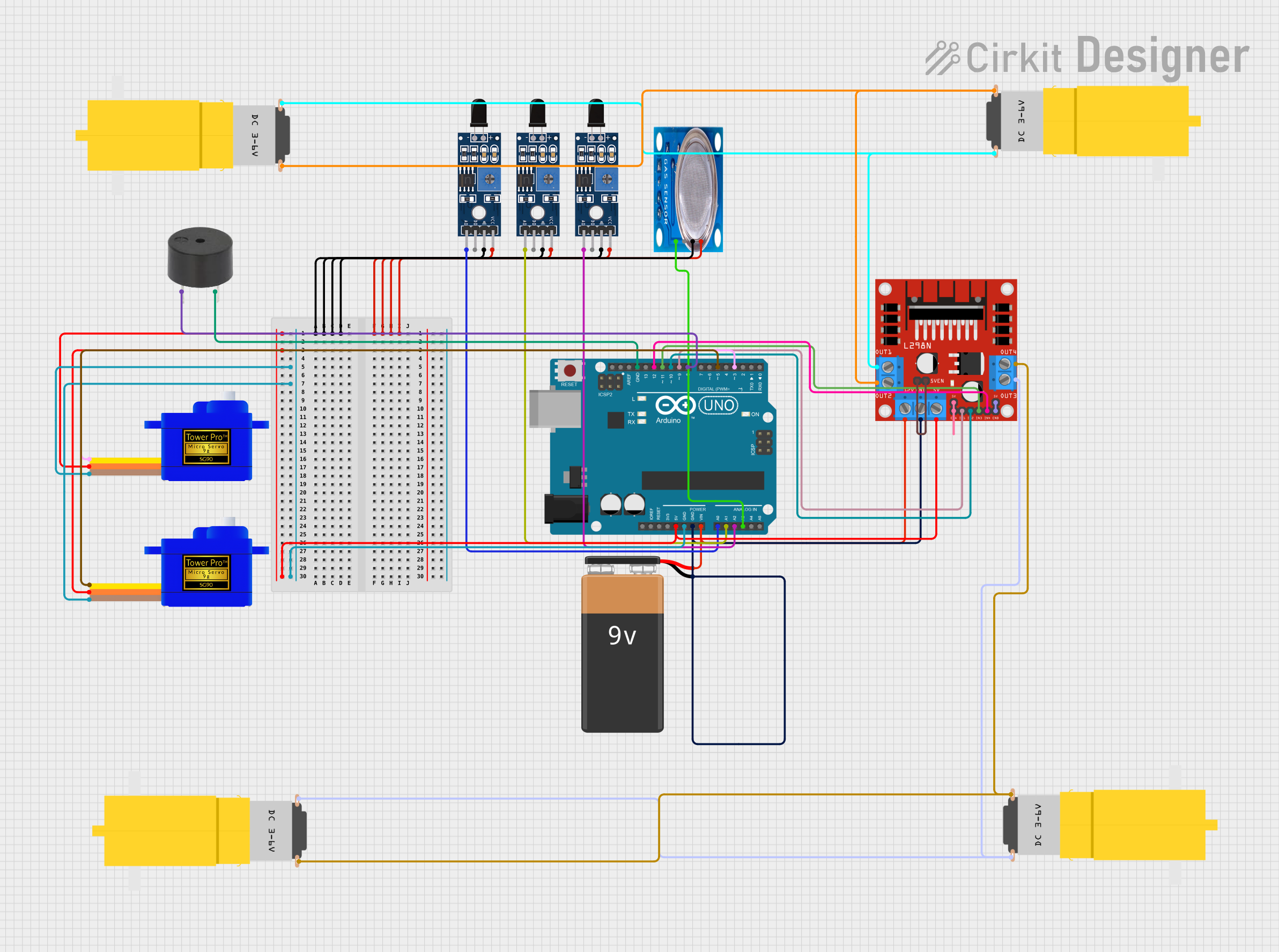
Arduino UNO Based Flame and Gas Detection Robot with Servo-Controlled Extinguishing System

Circuit Documentation
Summary
The circuit is designed to detect flames and gas presence using multiple sensors and respond accordingly. It includes flame sensors, a gas sensor, an Arduino UNO microcontroller, a buzzer for audible alerts, servomotors for mechanical movement, a motor driver to control DC motors, and a power source. The Arduino UNO reads sensor data to determine the presence of flames or gas and activates the motors and servos to take appropriate action, such as moving towards the flame or ventilating the area in case of gas detection.
Component List
Sensors
- Sensor SHT113 Flame: Flame detection sensor.
- MQ-5 Gas Sensor: Gas detection sensor for LPG, natural gas, and coal gas.
Microcontroller
- Arduino UNO: The main controller used to process sensor data and control other components.
Actuators
- L298N DC Motor Driver: Controls the direction and speed of DC motors.
- Motor Amarillo Motorreductor Hobby: DC motors used for movement.
- Servomotor SG90: Small servos used for precise control of mechanical parts.
Power Supply
- 9V Battery: Provides power to the circuit.
Output Devices
- Buzzer: Emits an audible alert when certain conditions are met.
Wiring Details
Sensor SHT113 Flame
- A0: Connected to Arduino UNO analog input pins (A0, A1, A2) for flame detection.
- D0: Not used in this circuit.
- GND: Common ground with other components.
- VCC: Power supply from Arduino UNO 5V pin.
MQ-5 Gas Sensor
- VCC: Power supply from Arduino UNO 5V pin.
- GND: Common ground with other components.
- Digi Out: Not used in this circuit.
- Analog out: Connected to Arduino UNO analog input pin A3.
Arduino UNO
- Digital Pins (D3, D5, D8, D9, D10, D11, D12): Control signals for servomotors, buzzer, and motor driver.
- Analog Pins (A0, A1, A2, A3): Receive sensor data from flame and gas sensors.
- 5V & GND: Power supply and ground for sensors, servomotors, and motor driver.
- Vin: Connected to the positive terminal of the 9V battery.
- GND: Connected to the negative terminal of the 9V battery.
L298N DC Motor Driver
- IN1, IN2, IN3, IN4: Control inputs from Arduino UNO digital pins (D9, D10, D11, D12).
- ENA, ENB: Enable pins for motor control, connected to 5V.
- OUT1, OUT2, OUT3, OUT4: Outputs to DC motors.
- 5V: Power supply from Arduino UNO 5V pin.
- GND: Common ground with Arduino UNO and 9V battery.
- 12V: Power supply from the 9V battery.
Motor Amarillo Motorreductor Hobby
- vcc: Connected to motor driver outputs (OUT2, OUT4).
- GND: Connected to motor driver outputs (OUT1, OUT3).
Servomotor SG90
- SIG: Control signal from Arduino UNO digital pins (D3, D5).
- VCC: Power supply from Arduino UNO 5V pin.
- GND: Common ground with other components.
Buzzer
- PIN: Control signal from Arduino UNO digital pin D8.
- GND: Common ground with other components.
Documented Code
#include <Servo.h>

// Pin Definitions
const int flameSensor1Pin = A0; // Front right
const int flameSensor2Pin = A1; // Center
const int flameSensor3Pin = A2; // Front left
const int gasSensorPin = A3;
const int buzzerPin = 8;
const int motor1Pin1 = 9;
const int motor1Pin2 = 10;
const int motor2Pin1 = 11;
const int motor2Pin2 = 12;
const int servo1Pin = 3;
const int servo2Pin = 5;

// Create Servo objects
Servo servo1;
Servo servo2;

// Thresholds
const int flameThreshold = 200; // Adjust based on calibration
const int gasThreshold = 400;   // Adjust based on calibration

void setup() {
  pinMode(buzzerPin, OUTPUT);
  pinMode(motor1Pin1, OUTPUT);
  pinMode(motor1Pin2, OUTPUT);
  pinMode(motor2Pin1, OUTPUT);
  pinMode(motor2Pin2, OUTPUT);

  servo1.attach(servo1Pin);
  servo2.attach(servo2Pin);
  servo1.write(0);
  servo2.write(0);

  Serial.begin(9600);
}

void loop() {
  int flame1 = analogRead(flameSensor1Pin);
  int flame2 = analogRead(flameSensor2Pin);
  int flame3 = analogRead(flameSensor3Pin);
  int gas = analogRead(gasSensorPin);

  // Check for flames
  if (flame1 > flameThreshold) {
    moveTowards(flame1);
    activateFireExtinguishing();
  } else if (flame2 > flameThreshold) {
    moveTowards(flame2);
    activateFireExtinguishing();
  } else if (flame3 > flameThreshold) {
    moveTowards(flame3);
    activateFireExtinguishing();
  }

  // Check for gas
  if (gas > gasThreshold) {
    moveBackAndForth();
    buzzBuzzer();
  }

  delay(100);
}

void moveTowards(int flame) {
  // Simple example: move forward if a flame is detected
  digitalWrite(motor1Pin1, HIGH);
  digitalWrite(motor1Pin2, LOW);
  digitalWrite(motor2Pin1, HIGH);
  digitalWrite(motor2Pin2, LOW);
}

void activateFireExtinguishing() {
  servo1.write(90);
  delay(10000);
  servo1.write(0);
  servo2.write(60);
  delay(13000);
  servo2.write(0);
  buzzBuzzer();
}

void moveBackAndForth() {
  // Move the car back and forth
  digitalWrite(motor1Pin1, LOW);
  digitalWrite(motor1Pin2, HIGH);
  digitalWrite(motor2Pin1, LOW);
  digitalWrite(motor2Pin2, HIGH);
  delay(5000);

  digitalWrite(motor1Pin1, HIGH);
  digitalWrite(motor1Pin2, LOW);
  digitalWrite(motor2Pin1, HIGH);
  digitalWrite(motor2Pin2, LOW);
  delay(5000);
}

void buzzBuzzer() {
  tone(buzzerPin, 1000); // Buzz sound at 1000Hz
  delay(15000); // Buzz for 15 seconds
  noTone(buzzerPin);
}
This code is responsible for reading sensor data, controlling the motors and servos, and activating the buzzer based on the sensor inputs. It includes functions for moving towards a detected flame, activating fire extinguishing procedures, moving back and forth in case of gas detection, and buzzing the buzzer as an alert. The thresholds for flame and gas detection can be calibrated as needed.