Cirkit Designer
Your all-in-one circuit design IDE
Home /
Project Documentation
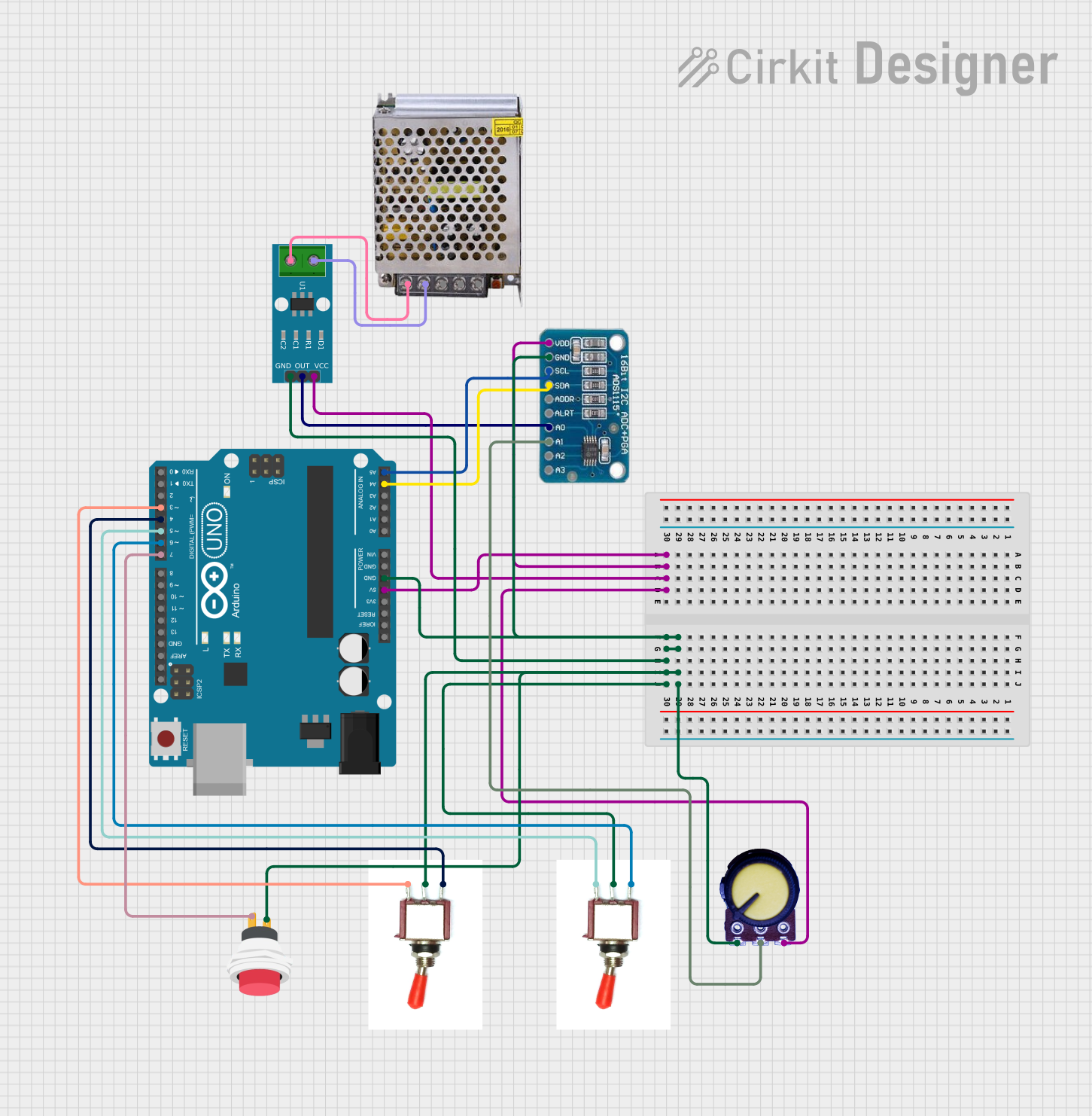
Arduino UNO with ADS1115 ADC and ACS712 Current Sensor Monitoring System

Circuit Documentation
Summary
This circuit is designed to measure current using an ACS712 Current Sensor and an ADS1115 ADC, with the ability to adjust settings using a potentiometer and toggle switches. An Arduino UNO serves as the central microcontroller, interfacing with the ADC and sensor, as well as reading inputs from the potentiometer, toggle switches, and a push switch. The circuit is powered by a 5V power supply.
Component List
ADS1115
- Description: A precision analog-to-digital converter (ADC) with 16-bit resolution.
- Pins: VDD, GND, SCL, SDA, ADDR, ALRT, A0, A1, A2, A3
Toggle Switch
- Description: A switch that can maintain its state either in ON or OFF position.
- Pins: Vcc, Sig, Gnd
Arduino UNO
- Description: A microcontroller board based on the ATmega328P.
- Pins: UNUSED, IOREF, Reset, 3.3V, 5V, GND, Vin, A0-A5, SCL, SDA, AREF, D0-D13
ACS712 Current Sensor 5A 20A 30A
- Description: A hall-effect-based linear current sensor.
- Pins: 1, 2, GND, OUT, VCC
Potentiometer
- Description: A three-terminal resistor with an adjustable center tap.
- Pins: GND, Output, VCC
2Pin Push Switch
- Description: A momentary push button switch.
- Pins: Input +, Output +
POWER SUPPLY 5V 5AMP
- Description: A power supply unit that provides 5V DC output.
- Pins: 220V Positive Pole (AC), 220V Negative Pole (AC), GND, GND (DC), 12V-24V Output (DC)
Wiring Details
ADS1115
- VDD connected to 5V (Arduino UNO)
- GND connected to GND (Common Ground)
- SCL connected to A5 (Arduino UNO)
- SDA connected to A4 (Arduino UNO)
- A0 connected to OUT (ACS712 Current Sensor)
- A1 connected to Output (Potentiometer)
Toggle Switch
- Vcc connected to D6 (Arduino UNO)
- Sig connected to GND (Common Ground)
- Gnd connected to D5 (Arduino UNO)
Arduino UNO
- GND connected to GND (Common Ground)
- 5V connected to VCC (Common Power)
ACS712 Current Sensor
- 1 connected to 220V Negative Pole (AC) (POWER SUPPLY)
- 2 connected to 220V Positive Pole (AC) (POWER SUPPLY)
- GND connected to GND (Common Ground)
- OUT connected to A0 (ADS1115)
- VCC connected to VCC (Common Power)
Potentiometer
- GND connected to GND (Common Ground)
- Output connected to A1 (ADS1115)
- VCC connected to VCC (Common Power)
2Pin Push Switch
- Input + connected to GND (Common Ground)
- Output + connected to D7 (Arduino UNO)
POWER SUPPLY 5V 5AMP
- Provides power to the circuit.
Documented Code
#include <Adafruit_ADS1X15.h>
#include <Wire.h>

Adafruit_ADS1115 ads;  // Create an instance of the ADS1115

// Pin Definitions
const int potPin = A1;           // Pin for potentiometer
const int toggleSwitch1Pin = 3;  // Pin for toggle switch 1 (corrected)
const int toggleSwitch2Pin = 4;  // Pin for toggle switch 2 (corrected)
const int pushSwitchPin = 7;     // Pin for push button (corrected)

// Variables to store values
int toggleSwitch1State = 0;      // Variable for toggle switch 1 state
int toggleSwitch2State = 0;      // Variable for toggle switch 2 state
int pushSwitchState = 0;         // Variable for push button state
float currentSetting = 0;        // Variable for potentiometer value

void setup() {
  // Start Serial communication for debugging
  Serial.begin(9600);

  // Initialize the ADS1115 ADC
  ads.begin();

  // Configure pins for switches
  pinMode(toggleSwitch1Pin, INPUT);    // Set toggle switch 1 pin as input
  pinMode(toggleSwitch2Pin, INPUT);    // Set toggle switch 2 pin as input
  pinMode(pushSwitchPin, INPUT_PULLUP); // Set push button pin as input with internal pull-up
}

void loop() {
  // Read the current from ACS712 via ADS1115
  int16_t rawADC = ads.readADC_SingleEnded(0);  // Read from A0 of ADS1115
  float voltage = rawADC * (4.096 / 32767.0);   // Convert raw ADC value to voltage
  float current = (voltage - 2.5) / 0.185;      // Convert voltage to current based on ACS712 (adjust based on your model)

  // Read the potentiometer value
  currentSetting = analogRead(potPin);          // Read potentiometer value from A1
  float knobValue = map(currentSetting, 0, 1023, 0, 100);  // Map to 0-100 range (adjust as needed)

  // Read the toggle switch states
  toggleSwitch1State = digitalRead(toggleSwitch1Pin);  // Read toggle switch 1 state
  toggleSwitch2State = digitalRead(toggleSwitch2Pin);  // Read toggle switch 2 state

  // Read the push button state
  pushSwitchState = digitalRead(pushSwitchPin); // Read push button state (LOW when pressed)

  // Send data to Serial for your custom software
  Serial.print("Current: ");
  Serial.print(current, 3);                     // Print current in Amps
  Serial.print(" A, Knob Value: ");
  Serial.print(knobValue);                      // Print potentiometer value as a percentage
  Serial.print(" %, Toggle Switch 1: ");
  Serial.print(toggleSwitch1State == HIGH ? "OFF" : "ON");  // Print toggle switch 1 state
  Serial.print(", Toggle Switch 2: ");
  Serial.print(toggleSwitch2State == HIGH ? "OFF" : "ON");  // Print toggle switch 2 state
  Serial.print(", Push Button: ");
  Serial.println(pushSwitchState == HIGH ? "Released" : "Pressed");  // Print push button state

  // Add a small delay to avoid spamming Serial
  delay(500);  // Adjust the delay as needed
}
This code is designed to run on an Arduino UNO and interfaces with an ADS1115 ADC to read current values from an ACS712 Current Sensor. It also reads the state of a potentiometer and several switches, outputting the data to the Serial Monitor for debugging or interfacing with custom software.