
ESP32-Based Smart Home Automation System with RFID and Solenoid Control
View and Edit Project In Cirkit Designer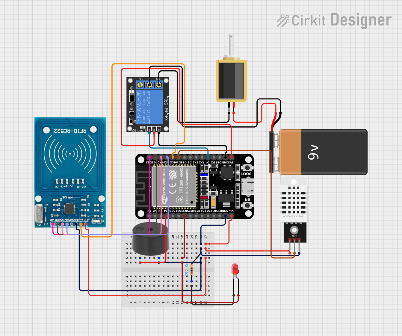
Circuit Documentation
Summary
This circuit involves an ESP32 microcontroller interfacing with various components including an LED, a buzzer, an RFID reader, a DHT22 sensor, a relay, a solenoid, and a 9V battery. The ESP32 controls these components to perform various tasks such as reading RFID tags, sensing temperature and humidity, and controlling a solenoid via a relay.
Component List
LED: Two Pin (red)
- Pins: cathode, anode
- Description: A red LED used for visual indication.
- Purpose in Circuit: Provides visual feedback.
ESP32 (30 pin)
- Pins: EN, VP, VN, D34, D35, D32, D33, D25, D26, D27, D14, D12, D13, GND, Vin, D23, D22, TX0, RX0, D21, D19, D18, D5, TX2, RX2, D4, D2, D15, 3V3
- Description: A microcontroller with Wi-Fi and Bluetooth capabilities.
- Purpose in Circuit: Central control unit for the circuit.
1-Channel Relay (5V 10A)
- Pins: NC, signal, C, power, NO, ground
- Description: A relay module used to control high-power devices.
- Purpose in Circuit: Controls the solenoid.
RFID-RC522
- Pins: VCC (3.3V), RST, GND, IRQ, MISO, MOSI, SCK, SDA
- Description: An RFID reader module.
- Purpose in Circuit: Reads RFID tags.
Buzzer
- Pins: PIN, GND
- Description: A piezoelectric buzzer.
- Purpose in Circuit: Provides audible feedback.
Solenoid
- Pins: pin1, pin2
- Description: An electromechanical solenoid.
- Purpose in Circuit: Performs mechanical actions.
9V Battery
- Pins: -, +
- Description: A 9V battery.
- Purpose in Circuit: Provides power to the solenoid via the relay.
Resistor
- Pins: pin1, pin2
- Description: A resistor with a resistance of 200 Ohms.
- Purpose in Circuit: Limits current to the LED.
DHT22
- Pins: +, Out, -
- Description: A temperature and humidity sensor.
- Purpose in Circuit: Measures temperature and humidity.
Wiring Details
LED: Two Pin (red)
- cathode is connected to pin1 of the Resistor.
- anode is connected to D33 of the ESP32.
ESP32 (30 pin)
- D33 is connected to the anode of the LED.
- D34 is connected to the PIN of the Buzzer.
- GND is connected to:
- pin2 of the Resistor
- GND of the Buzzer
- GND of the RFID-RC522
- - of the DHT22
- ground of the 1-Channel Relay
- Vin is connected to:
- VCC (3.3V) of the RFID-RC522
- + of the DHT22
- D23 is connected to SDA of the RFID-RC522.
- D22 is connected to SCK of the RFID-RC522.
- TX0 is connected to MOSI of the RFID-RC522.
- RX0 is connected to MISO of the RFID-RC522.
- D21 is connected to RST of the RFID-RC522.
- D19 is connected to Out of the DHT22.
- D4 is connected to signal of the 1-Channel Relay.
- 3V3 is connected to power of the 1-Channel Relay.
1-Channel Relay (5V 10A)
- signal is connected to D4 of the ESP32.
- ground is connected to GND of the ESP32.
- power is connected to 3V3 of the ESP32.
- C is connected to - of the 9V Battery.
- NO is connected to pin1 of the Solenoid.
RFID-RC522
- VCC (3.3V) is connected to Vin of the ESP32.
- GND is connected to GND of the ESP32.
- SDA is connected to D23 of the ESP32.
- SCK is connected to D22 of the ESP32.
- MOSI is connected to TX0 of the ESP32.
- MISO is connected to RX0 of the ESP32.
- RST is connected to D21 of the ESP32.
Buzzer
- PIN is connected to D34 of the ESP32.
- GND is connected to pin2 of the Resistor.
Solenoid
- pin1 is connected to NO of the 1-Channel Relay.
- pin2 is connected to + of the 9V Battery.
9V Battery
- - is connected to C of the 1-Channel Relay.
- + is connected to pin2 of the Solenoid.
Resistor
- pin1 is connected to cathode of the LED.
- pin2 is connected to:
- GND of the Buzzer
- GND of the RFID-RC522
- - of the DHT22
- GND of the ESP32
DHT22
- + is connected to Vin of the ESP32.
- Out is connected to D19 of the ESP32.
- - is connected to GND of the ESP32.
Documented Code
sketch.ino
void setup() {
  // put your setup code here, to run once:

}

void loop() {
  // put your main code here, to run repeatedly:

}
documentation.txt