
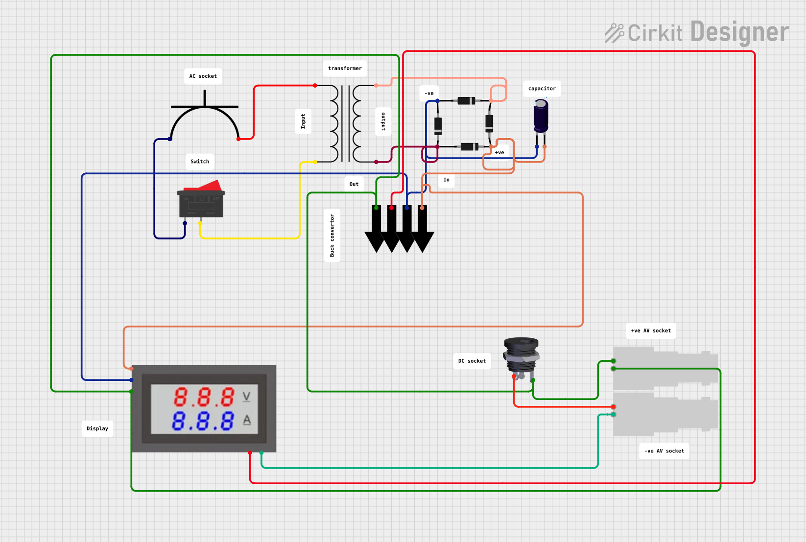
Circuit Documentation
Summary
The circuit described by the provided inputs appears to be a power supply circuit that converts AC voltage to a rectified DC output. It includes a power transformer for voltage step-down or isolation, a series of diodes forming a bridge rectifier to convert AC to DC, an electrolytic capacitor for voltage smoothing, a digital voltmeter/ammeter for monitoring voltage and current, and various connectors and switches for interfacing and control.
Component List
Power Transformer
- Description: A transformer used to step down or isolate the AC voltage.
- Pins: Primary (x2), Secondary (x2)
Diodes (x4)
- Description: Semiconductor devices that allow current to flow in one direction only, used here to form a bridge rectifier.
- Pins: Anode, Cathode
AC Power Plug
- Description: The input connector for AC power.
- Pins: Positive Terminal, Negative Terminal
Rocker Switch
- Description: A switch to control the power flow in the circuit.
- Pins: 1, 2
Mini Digital Volt/Ammeter
- Description: A device to measure and display the voltage and current of the circuit.
- Pins: Gnd, Vin, Vread, Vsupply
Electrolytic Capacitor
- Description: A capacitor used for filtering and smoothing the rectified DC voltage.
- Pins: -, +
- Properties: Capacitance: 1 µF (0.000001 Farads)
DC Female Jack
- Description: A connector for DC power output.
- Pins: Negative, Plug Detect, Positive
Female BNC Connectors (x2)
- Description: Connectors used for signal input/output.
- Pins: Pin 1, Pin 2
Arrow-Connectors (x4)
- Description: Used to indicate the flow of current or to denote connections extending off the board.
Comments (x12)
- Description: Text fields used to add notes or labels on the schematic for clarification.
Wiring Details
Power Transformer
- Primary 1 connected to AC Power Plug Positive Terminal.
- Primary 2 connected to Rocker Switch Pin 2.
- Secondary 3 connected to Diode Anode (Diode 1) and Diode Cathode (Diode 2).
- Secondary 4 connected to Diode Cathode (Diode 3) and Diode Anode (Diode 4).
Diodes
- Diode 1 Anode connected to Power Transformer Secondary 3.
- Diode 2 Cathode connected to Power Transformer Secondary 3.
- Diode 3 Cathode connected to Power Transformer Secondary 4.
- Diode 4 Anode connected to Power Transformer Secondary 4.
- The anodes of Diode 2 and Diode 3 are connected together and to Mini Digital Volt/Ammeter Vsupply, Electrolytic Capacitor -, and Arrow-connector (Net 6).
- The cathodes of Diode 1 and Diode 4 are connected together and to Mini Digital Volt/Ammeter Vread, Electrolytic Capacitor +, and Arrow-connector (Net 7).
AC Power Plug
- Positive Terminal connected to Power Transformer Primary 1.
- Negative Terminal connected to Rocker Switch Pin 1.
Rocker Switch
- Pin 1 connected to AC Power Plug Negative Terminal.
- Pin 2 connected to Power Transformer Primary 2.
Mini Digital Volt/Ammeter
- Gnd connected to Female BNC Pin 1, Female BNC Pin 2, and Arrow-connector (Net 8).
- Vin connected to Female BNC Pin 2.
- Vread connected to the cathodes of Diode 1 and Diode 4, Electrolytic Capacitor +, and Arrow-connector (Net 7).
- Vsupply connected to the anodes of Diode 2 and Diode 3, Electrolytic Capacitor -, and Arrow-connector (Net 6).
Electrolytic Capacitor
-
- (Negative) connected to the anodes of Diode 2 and Diode 3, Mini Digital Volt/Ammeter Vsupply, and Arrow-connector (Net 6).
-
- (Positive) connected to the cathodes of Diode 1 and Diode 4, Mini Digital Volt/Ammeter Vread, and Arrow-connector (Net 7).
DC Female Jack
- Negative connected to Female BNC Pin 1.
- Positive connected to Female BNC Pin 1 and Mini Digital Volt/Ammeter Gnd.
Female BNC Connectors
- Pin 1 of BNC 1 connected to Pin 2 of BNC 1, Mini Digital Volt/Ammeter Gnd, and DC Female Jack Positive.
- Pin 2 of BNC 1 connected to Mini Digital Volt/Ammeter Vin.
- Pin 1 of BNC 2 connected to DC Female Jack Negative.
- Pin 2 of BNC 2 connected to Mini Digital Volt/Ammeter Gnd.
Documented Code
There is no embedded code provided for any microcontrollers in this circuit. If there were microcontrollers or other programmable devices included, this section would contain the documented code for each device, including descriptions of functionality and any relevant algorithms or logic used.