Cirkit Designer
Your all-in-one circuit design IDE
Home /
Project Documentation
LM386 Amplifier Circuit with 3.5mm Audio Input and Loudspeaker Output
Circuit Documentation
Summary
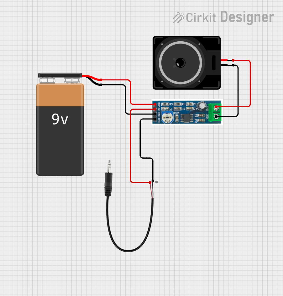
This document provides a detailed overview of an audio amplification circuit. The circuit is designed to amplify an audio signal from a 3.5mm audio jack and output it through a loudspeaker. The circuit is powered by a 9V battery and uses an LM386 audio amplifier module to amplify the audio signal. The circuit does not include any microcontroller or embedded code.
Component List
LM386 Audio Amplifier Module
- Description: A low-voltage audio power amplifier used for amplifying audio signals.
- Pins: VCC, IN, GND, OUT
Loudspeaker
- Description: An electroacoustic transducer that converts an electrical audio signal into a corresponding sound.
- Pins: pin1, pin2
9V Battery
- Description: A standard 9V battery used as the power source for the circuit.
- Pins: -, +
3.5mm Audio Jack 3 Pin
- Description: A common audio connector used for transmitting audio signals.
- Pins: L, R, GND
Wiring Details
LM386 Audio Amplifier Module
- VCC: Connected to the positive terminal (+) of the 9V Battery.
- IN: Connected to the left channel (L) of the 3.5mm Audio Jack.
- GND: Connected to the negative terminal (-) of the 9V Battery and the ground (GND) of the 3.5mm Audio Jack.
- OUT: Connected to pin2 of the Loudspeaker.
Loudspeaker
- pin1: Connected to the ground (GND) of the LM386 Audio Amplifier Module.
- pin2: Connected to the output (OUT) of the LM386 Audio Amplifier Module.
9V Battery
- +: Connected to the VCC of the LM386 Audio Amplifier Module.
- -: Connected to the GND of the LM386 Audio Amplifier Module.
3.5mm Audio Jack 3 Pin
- L: Connected to the input (IN) of the LM386 Audio Amplifier Module.
- R: Not connected in this circuit.
- GND: Connected to the ground (GND) of the LM386 Audio Amplifier Module.
Documented Code
There is no embedded code associated with this circuit as it does not include any programmable components or microcontrollers.