Cirkit Designer
Your all-in-one circuit design IDE
Home /
Project Documentation
Arduino UNO and L298N Motor Driver Controlled Dual DC Motor System with Battery Power
Circuit Documentation
Summary
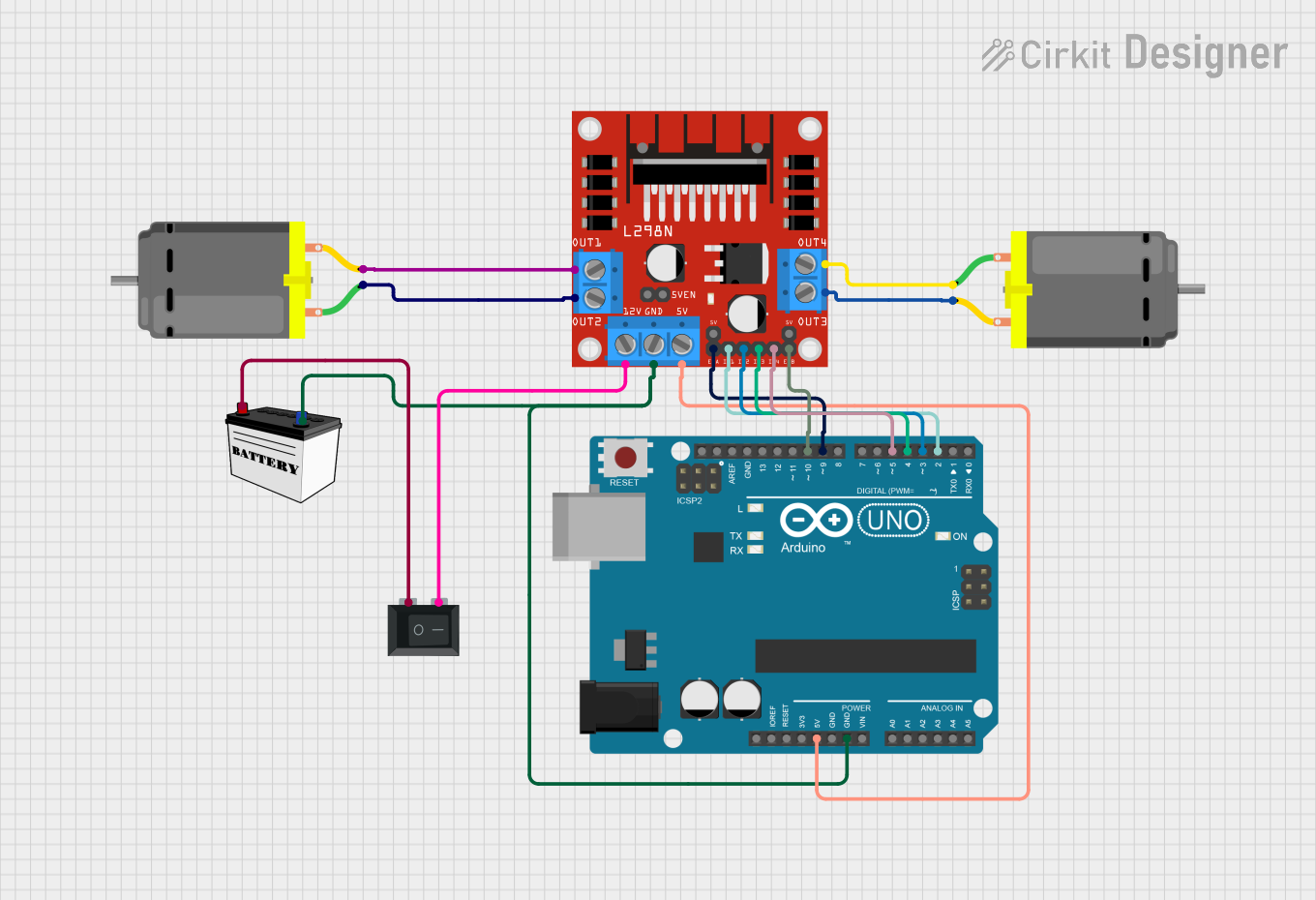
This circuit is designed to control two DC motors using an Arduino UNO and an L298N motor driver. The motors are powered by a 12V battery and can be controlled via PWM signals from the Arduino. A rocker switch is used to control the power supply to the motor driver.
Component List
L298N DC Motor Driver
- Description: A dual H-bridge motor driver that allows control of two DC motors.
- Pins: OUT1, OUT2, 12V, GND, 5V, OUT3, OUT4, 5V-ENA-JMP-I, 5V-ENA-JMP-O, +5V-J1, +5V-J2, ENA, IN1, IN2, IN3, IN4, ENB
DC Motor (Motor A)
- Description: A standard DC motor.
- Pins: pin 1, pin 2
DC Motor (Motor B)
- Description: A standard DC motor.
- Pins: pin 1, pin 2
Arduino UNO
- Description: A microcontroller board based on the ATmega328P.
- Pins: UNUSED, IOREF, Reset, 3.3V, 5V, GND, Vin, A0, A1, A2, A3, A4, A5, SCL, SDA, AREF, D13, D12, D11, D10, D9, D8, D7, D6, D5, D4, D3, D2, D1, D0
12V Battery (Small Size)
- Description: A small-sized 12V battery.
- Pins: VCC, GND
Rocker Switch (SPST)
- Description: A single-pole single-throw (SPST) rocker switch.
- Pins: 1, 2
Wiring Details
L298N DC Motor Driver
- 5V connected to 5V of Arduino UNO
- GND connected to GND of Arduino UNO and GND of 12V Battery
- ENA connected to D9 of Arduino UNO
- ENB connected to D10 of Arduino UNO
- IN1 connected to D2 of Arduino UNO
- IN2 connected to D3 of Arduino UNO
- IN3 connected to D4 of Arduino UNO
- IN4 connected to D5 of Arduino UNO
- OUT1 connected to pin 2 of DC Motor (Motor B)
- OUT2 connected to pin 1 of DC Motor (Motor B)
- OUT3 connected to pin 2 of DC Motor (Motor A)
- OUT4 connected to pin 1 of DC Motor (Motor A)
- 12V connected to pin 2 of Rocker Switch (SPST)
DC Motor (Motor A)
- pin 1 connected to OUT4 of L298N DC Motor Driver
- pin 2 connected to OUT3 of L298N DC Motor Driver
DC Motor (Motor B)
- pin 1 connected to OUT2 of L298N DC Motor Driver
- pin 2 connected to OUT1 of L298N DC Motor Driver
Arduino UNO
- 5V connected to 5V of L298N DC Motor Driver
- GND connected to GND of L298N DC Motor Driver and GND of 12V Battery
- D9 connected to ENA of L298N DC Motor Driver
- D10 connected to ENB of L298N DC Motor Driver
- D2 connected to IN1 of L298N DC Motor Driver
- D3 connected to IN2 of L298N DC Motor Driver
- D4 connected to IN3 of L298N DC Motor Driver
- D5 connected to IN4 of L298N DC Motor Driver
12V Battery (Small Size)
- VCC connected to pin 1 of Rocker Switch (SPST)
- GND connected to GND of Arduino UNO and GND of L298N DC Motor Driver
Rocker Switch (SPST)
- pin 1 connected to VCC of 12V Battery
- pin 2 connected to 12V of L298N DC Motor Driver
Documented Code
Arduino UNO Code
/*
 * This Arduino sketch controls two DC motors connected to an L298N motor driver.
 * The motors are set to spin in opposite directions, and their speed (RPM) can
 * be controlled using PWM signals. The motor driver is connected to the Arduino
 * as follows:
 * - ENA (Motor A enable) -> D9
 * - IN1 (Motor A input 1) -> D2
 * - IN2 (Motor A input 2) -> D3
 * - ENB (Motor B enable) -> D10
 * - IN3 (Motor B input 1) -> D4
 * - IN4 (Motor B input 2) -> D5
 */

// Define motor control pins
const int ENA = 9;
const int IN1 = 2;
const int IN2 = 3;
const int ENB = 10;
const int IN3 = 4;
const int IN4 = 5;

void setup() {
  // Set all the motor control pins to output mode
  pinMode(ENA, OUTPUT);
  pinMode(IN1, OUTPUT);
  pinMode(IN2, OUTPUT);
  pinMode(ENB, OUTPUT);
  pinMode(IN3, OUTPUT);
  pinMode(IN4, OUTPUT);

  // Initialize motors to spin in opposite directions
  digitalWrite(IN1, HIGH);
  digitalWrite(IN2, LOW);
  digitalWrite(IN3, LOW);
  digitalWrite(IN4, HIGH);
}

void loop() {
  // Set motor speed using PWM (0-255)
  int speed = 128; // Example speed value, can be adjusted
  analogWrite(ENA, speed);
  analogWrite(ENB, speed);

  // Add any additional logic here if needed
}
DC Motor (Motor A) Code
void setup() {
  // put your setup code here, to run once:

}

void loop() {
  // put your main code here, to run repeatedly:

}
DC Motor (Motor B) Code
void setup() {
  // put your setup code here, to run once:

}

void loop() {
  // put your main code here, to run repeatedly:

}