Cirkit Designer
Your all-in-one circuit design IDE
Home /
Project Documentation
Arduino UNO WiFi with I2C LCD and LDR Light Sensor
Circuit Documentation
Summary of the Circuit
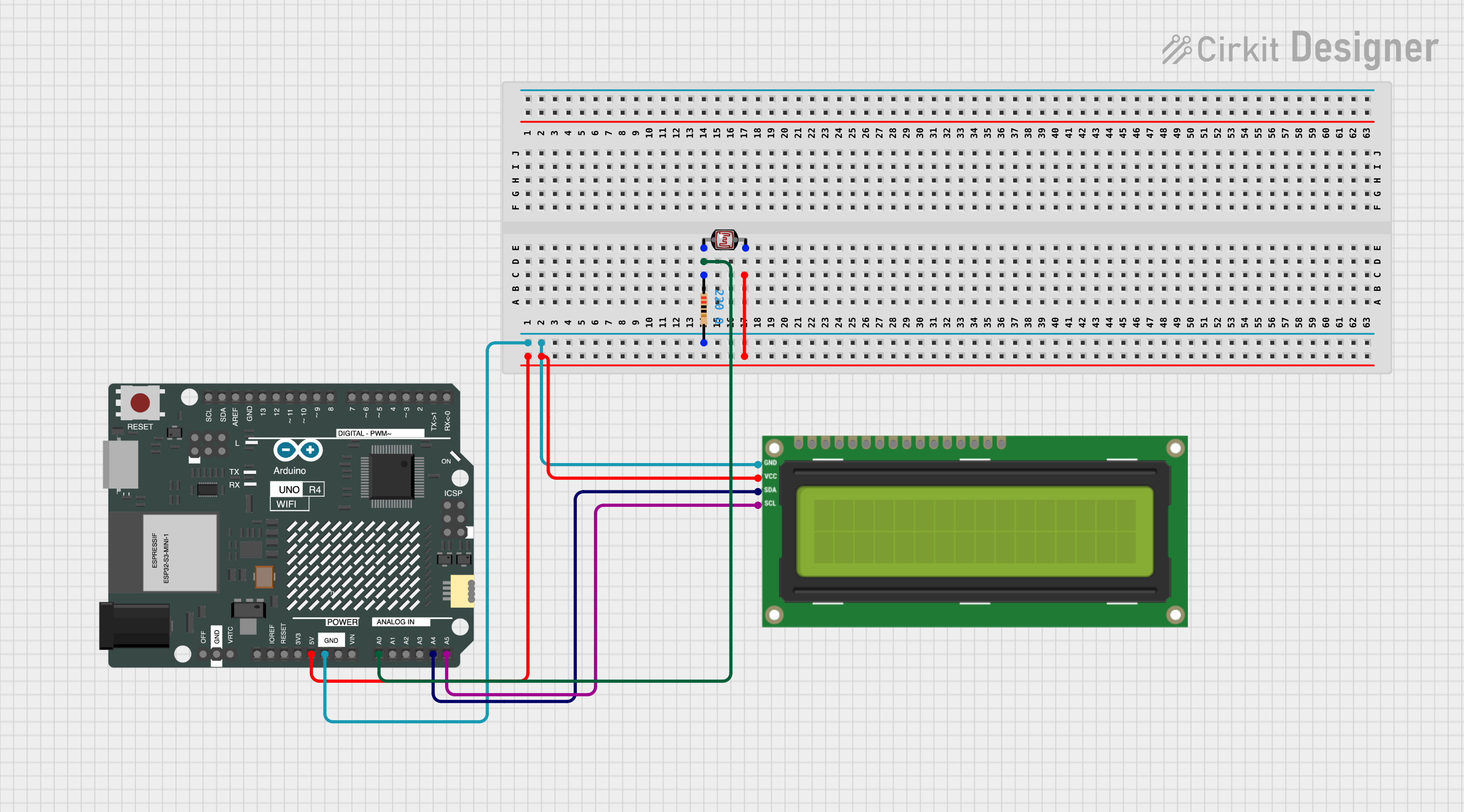
This circuit consists of an Arduino UNO R4 WiFi microcontroller interfaced with an I2C LCD 16x2 screen and a photocell (LDR) sensor. The photocell is used to measure the ambient light level, and the LCD screen displays the light intensity in human-readable form. A resistor is connected in series with the photocell to form a voltage divider, which allows the Arduino to read the light levels as an analog voltage on one of its analog input pins.
Component List
I2C LCD 16x2 Screen
- Description: A 16x2 character LCD display that uses the I2C communication protocol.
- Pins: SCL, SDA, VCC (5V), GND, VDD, VO, RS, RW, E, D0, D1, D2, D3, D4, D5, D6, D7, BLA, BLK
Arduino UNO R4 WiFi
- Description: A microcontroller board based on the ATmega328P with built-in WiFi capability.
- Pins: OFF, GND, VRTC, IIC0_SCL, IIC0_SDA, 3V3, GPIO 41, GPIO 0, GPIO 42, GPIO 43, GPIO 44, BOOT, IOREF, RESET, 5V, VIN, A0, A1, A2, A3, A4, A5, RSPCKA, CIPO, COPI, D0/RX, D1/TX, D2, D3, D4, D5, D6, D7, D8, D9, D10, D11, D12, D13, AREF, SDA, SCL
Photocell (LDR)
- Description: A light-dependent resistor whose resistance changes with the amount of light it is exposed to.
- Pins: pin 0, pin 1
Resistor
- Description: A passive two-terminal electrical component that implements electrical resistance as a circuit element.
- Resistance: 220 Ohms
Wiring Details
I2C LCD 16x2 Screen
- SCL: Connected to Arduino's A5 (SCL)
- SDA: Connected to Arduino's A4 (SDA)
- VCC (5V): Connected to Arduino's 5V
- GND: Connected to Arduino's GND
Arduino UNO R4 WiFi
- A0: Connected to one end of the photocell (LDR) and one end of the resistor (forming a voltage divider)
- 5V: Provides power to the photocell (LDR) and the I2C LCD 16x2 Screen
- GND: Common ground for the circuit, connected to the other end of the resistor and the I2C LCD 16x2 Screen
- A4 (SDA): Connected to SDA of the I2C LCD 16x2 Screen
- A5 (SCL): Connected to SCL of the I2C LCD 16x2 Screen
Photocell (LDR)
- pin 0: Connected to Arduino's A0 and one end of the resistor
- pin 1: Connected to Arduino's 5V
Resistor
- pin1: Connected to Arduino's A0 and one end of the photocell (LDR)
- pin2: Connected to Arduino's GND
Documented Code
#include <Wire.h>
#include <LiquidCrystal_I2C.h>

// Define the I2C address for the 16x2 LCD (often 0x27 or 0x3F for I2C LCDs)
LiquidCrystal_I2C lcd(0x27, 16, 2);

int sensorPin = A0;  // Pin where LDR is connected
int sensorValue = 0; // Variable to store the value coming from the sensor

void setup() {
  // Initialize the LCD
  lcd.init();
  lcd.backlight();

  // Start serial communication
  Serial.begin(9600);
  lcd.setCursor(0, 0);
  lcd.print("Light Level: ");
}

void loop() {
  // Read the value from the photoresistor
  sensorValue = analogRead(sensorPin);

  // Print the sensor value to the Serial Monitor
  Serial.print("Photoresistor Value: ");
  Serial.println(sensorValue);

  // Determine the light level based on the sensor value
  String lightLevel;
  if (sensorValue < 200) {
    lightLevel = "Dark";
  } else if (sensorValue < 400) {
    lightLevel = "Partially Dark";
  } else if (sensorValue < 600) {
    lightLevel = "Medium";
  } else if (sensorValue < 800) {
    lightLevel = "Fully Lit";
  } else {
    lightLevel = "Brightly Lit";
  }

  // Display the light level on the LCD
  lcd.setCursor(0, 1);  // Set the cursor to the second line
  lcd.print("                "); // Clear the second line
  lcd.setCursor(0, 1);  // Reset cursor
  lcd.print(lightLevel); // Display the light level

  // Wait 1 second before the next reading (for ease of testing)
  delay(1000);
}
This code initializes the LCD and sets up the Arduino to read the analog value from the photocell (LDR). It then prints the raw sensor value to the Serial Monitor and displays a qualitative light level on the LCD based on the sensor reading. The light level is updated every second.