Cirkit Designer
Your all-in-one circuit design IDE
Home /
Project Documentation
Arduino-Based MIDI-Controlled Solenoid Actuator with LED Display
Circuit Documentation
Summary
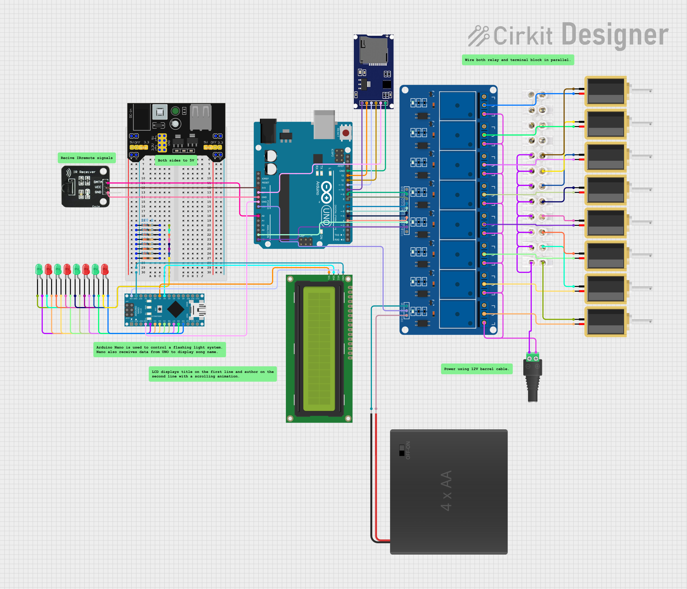
This circuit is designed to control multiple LEDs and solenoids using an Arduino UNO and an Arduino Nano. The circuit also includes an IR receiver for remote control, an SD card module for storing MIDI files, and an I2C LCD for displaying song information. The Arduino UNO handles the MIDI file playback and relay control, while the Arduino Nano manages the LED display and LCD screen.
Component List
Arduino UNO
- Description: A microcontroller board based on the ATmega328P.
- Pins: UNUSED, IOREF, Reset, 3.3V, 5V, GND, Vin, A0, A1, A2, A3, A4, A5, SCL, SDA, AREF, D13, D12, D11, D10, D9, D8, D7, D6, D5, D4, D3, D2, D1, D0
Arduino Nano
- Description: A small, complete, and breadboard-friendly board based on the ATmega328P.
- Pins: D1/TX, D0/RX, RESET, GND, D2, D3, D4, D5, D6, D7, D8, D9, D10, D11/MOSI, D12/MISO, VIN, 5V, A7, A6, A5, A4, A3, A2, A1, A0, AREF, 3V3, D13/SCK
2.1mm Barrel Jack with Terminal Block
- Description: A power connector for supplying voltage to the circuit.
- Pins: POS, NEG
MB102 Breadboard Power Supply Module 3.3V/5V
- Description: A power supply module that provides 3.3V and 5V outputs.
- Pins: VCC, GND, 3.3V, 5V
16x2 I2C LCD
- Description: A 16x2 character LCD with I2C interface.
- Pins: GND, VCC, SDA, SCL
IR Receiver
- Description: An infrared receiver for remote control.
- Pins: DATA, VCC, GND
5V 8 Channel Relay Module
- Description: A relay module for controlling high-power devices.
- Pins: NC, COM, NO, GND, VCC, JD-VCC, IN8, IN7, IN6, IN5, IN4, IN3, IN2, IN1
SD Module
- Description: An SD card module for storing and reading files.
- Pins: CS, SCK, MOSI, MISO, VCC, GND
LED: Two Pin (red)
- Description: A red LED with two pins.
- Pins: cathode, anode
LED: Two Pin (green)
- Description: A green LED with two pins.
- Pins: cathode, anode
Resistor
- Description: A resistor with a resistance of 220 Ohms.
- Pins: pin1, pin2
Solenoid
- Description: An electromechanical solenoid.
- Pins: pin1, pin2
4xAA Battery Holder
- Description: A battery holder for four AA batteries.
- Pins: POS, NEG
Terminal Block 3A 12 Position Dual Row
- Description: A terminal block for connecting multiple wires.
- Pins: None
Wiring Details
Arduino UNO
- 3.3V to IR Receiver VCC
- 5V to SD Module VCC
- GND to IR Receiver GND
- GND to Arduino Nano GND
- Vin to 5V 8 Channel Relay Module VCC
- A0 to IR Receiver DATA
- A4 to 5V 8 Channel Relay Module IN7
- A5 to 5V 8 Channel Relay Module IN8
- GND to SD Module GND
- D13 to SD Module SCK
- D12 to SD Module MISO
- D11 to SD Module MOSI
- D10 to SD Module CS
- D9 to 5V 8 Channel Relay Module IN1
- D8 to 5V 8 Channel Relay Module IN2
- D7 to 5V 8 Channel Relay Module IN3
- D6 to 5V 8 Channel Relay Module IN4
- D5 to 5V 8 Channel Relay Module IN5
- D4 to 5V 8 Channel Relay Module IN6
Arduino Nano
- GND to Common Ground
- VIN to 16x2 I2C LCD VCC
- A4 to 16x2 I2C LCD SDA
- A5 to 16x2 I2C LCD SCL
- D2 to Green LED anode
- D3 to Red LED anode
- D4 to Green LED anode
- D5 to Red LED anode
- D6 to Green LED anode
- D7 to Red LED anode
- D8 to Green LED anode
- D9 to Red LED anode
2.1mm Barrel Jack with Terminal Block
- POS to 5V 8 Channel Relay Module NO
- NEG to Common Ground
MB102 Breadboard Power Supply Module 3.3V/5V
- VCC to Common VCC
- GND to Common Ground
- 3.3V to Common 3.3V
- 5V to Common 5V
16x2 I2C LCD
- GND to Common Ground
- VCC to Arduino Nano VIN
- SDA to Arduino Nano A4
- SCL to Arduino Nano A5
IR Receiver
- DATA to Arduino UNO A0
- VCC to Arduino UNO 3.3V
- GND to Arduino UNO GND
5V 8 Channel Relay Module
- NC to Not Connected
- COM to Solenoid pin2
- NO to 2.1mm Barrel Jack POS
- GND to Common Ground
- VCC to Arduino UNO Vin
- JD-VCC to 4xAA Battery Holder POS
- IN1 to Arduino UNO D9
- IN2 to Arduino UNO D8
- IN3 to Arduino UNO D7
- IN4 to Arduino UNO D6
- IN5 to Arduino UNO D5
- IN6 to Arduino UNO D4
- IN7 to Arduino UNO A4
- IN8 to Arduino UNO A5
SD Module
- CS to Arduino UNO D10
- SCK to Arduino UNO D13
- MOSI to Arduino UNO D11
- MISO to Arduino UNO D12
- VCC to Arduino UNO 5V
- GND to Arduino UNO GND
LED: Two Pin (red)
- cathode to Resistor pin2
- anode to Arduino Nano D3
LED: Two Pin (green)
- cathode to Resistor pin2
- anode to Arduino Nano D2
Resistor
- pin1 to Common Ground
- pin2 to LED cathode
Solenoid
- pin1 to Terminal Block 3A 12 Position Dual Row
- pin2 to 5V 8 Channel Relay Module COM
4xAA Battery Holder
- POS to 5V 8 Channel Relay Module JD-VCC
- NEG to Common Ground
Terminal Block 3A 12 Position Dual Row
- Connected to Solenoid pin1
Documented Code
Arduino UNO Code
#include <SoftwareSerial.h>
#include "SdFat.h"
#include <MD_MIDIFile.h>
#include <IRremote.h>

// Define TX pin for TXOnlySerial
SoftwareSerial mySerial(2, 3); // RX, TX

#define ARRAY_SIZE(a) (sizeof(a) / sizeof((a)[0]))

const uint8_t NOTE_SIZE = 1; // Number of items in each note listing

// Define a structure to contain all the related data for executing a note
typedef struct
{
  const int pin;              // Motor output relay pin
  const int note[NOTE_SIZE];