
Arduino UNO-Based Smart Security System with RFID, Fingerprint Sensor, and Wi-Fi Connectivity
View and Edit Project In Cirkit Designer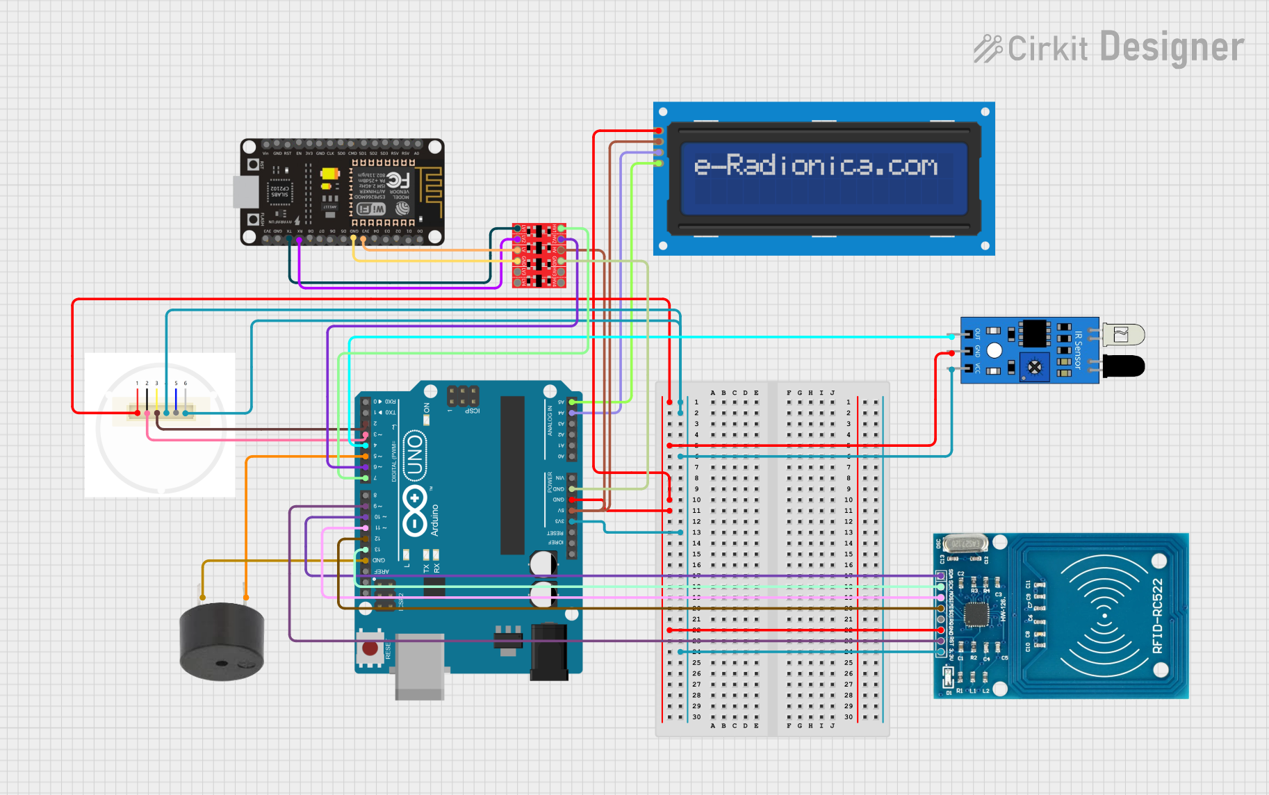
Circuit Documentation
Summary
This document provides a detailed overview of a circuit that includes various sensors, a display, a buzzer, and communication modules. The circuit is controlled by an Arduino UNO microcontroller and includes components such as an IR sensor, LCD screen, buzzer, RFID module, capacitive fingerprint sensor, and an ESP8266 NodeMCU. The components are interconnected to perform specific functions, and the microcontroller is programmed to manage these components.
Component List
IR Sensor
- Description: Infrared sensor used for detecting objects or motion.
- Pins: out, gnd, vcc
LCD Screen 16x2 I2C
- Description: 16x2 character LCD display with I2C interface.
- Pins: SCL, SDA, VCC, GND
Buzzer
- Description: Simple buzzer for audio feedback.
- Pins: PIN, GND
RFID-RC522
- Description: RFID reader module for reading RFID tags.
- Pins: VCC (3.3V), RST, GND, IRQ, MISO, MOSI, SCK, SDA
Arduino UNO
- Description: Microcontroller board based on the ATmega328P.
- Pins: UNUSED, IOREF, Reset, 3.3V, 5V, GND, Vin, A0, A1, A2, A3, A4, A5, SCL, SDA, AREF, D13, D12, D11, D10, D9, D8, D7, D6, D5, D4, D3, D2, D1, D0
Bi-Directional Logic Level Converter
- Description: Converts voltage levels between different components.
- Pins: HV1, HV2, HV, GND, HV3, HV4, LV1, LV2, LV, LV3, LV4
Capacitive Fingerprint Sensor
- Description: Sensor for capturing and recognizing fingerprints.
- Pins: GND, RX, TX, VIN, IRQ, Power
ESP8266 NodeMCU
- Description: Wi-Fi module for wireless communication.
- Pins: D0, D1, D2, D3, D4, 3V3, GND, D5, D6, D7, D8, RX, TX, A0, RSV, SD3, SD2, SD1, CMD, SD0, CLK, EN, RST, VIN
Wiring Details
IR Sensor
- gnd connected to GND of Arduino UNO
- vcc connected to 3.3V of Arduino UNO
- out connected to D4 of Arduino UNO
LCD Screen 16x2 I2C
- GND connected to GND of Arduino UNO
- VCC connected to 5V of Arduino UNO
- SCL connected to A5 of Arduino UNO
- SDA connected to A4 of Arduino UNO
Buzzer
- GND connected to GND of Arduino UNO
- PIN connected to D5 of Arduino UNO
RFID-RC522
- GND connected to GND of Arduino UNO
- VCC (3.3V) connected to 3.3V of Arduino UNO
- RST connected to D9 of Arduino UNO
- MISO connected to D12 of Arduino UNO
- MOSI connected to D11 of Arduino UNO
- SCK connected to D13 of Arduino UNO
- SDA connected to D10 of Arduino UNO
Bi-Directional Logic Level Converter
- GND connected to GND of Arduino UNO
- HV connected to 5V of Arduino UNO
- HV1 connected to D7 of Arduino UNO
- HV2 connected to D6 of Arduino UNO
- LV connected to 3V3 of ESP8266 NodeMCU
- LV1 connected to TX of ESP8266 NodeMCU
- LV2 connected to RX of ESP8266 NodeMCU
Capacitive Fingerprint Sensor
- GND connected to GND of Arduino UNO
- VIN connected to 3.3V of Arduino UNO
- Power connected to 3.3V of Arduino UNO
- RX connected to D3 of Arduino UNO
- TX connected to D2 of Arduino UNO
ESP8266 NodeMCU
- GND connected to GND of Bi-Directional Logic Level Converter
- 3V3 connected to LV of Bi-Directional Logic Level Converter
- TX connected to LV1 of Bi-Directional Logic Level Converter
- RX connected to LV2 of Bi-Directional Logic Level Converter
Code Documentation
Arduino UNO Code
void setup() {
  // put your setup code here, to run once:

}

void loop() {
  // put your main code here, to run repeatedly:

}
This code is a basic template for the Arduino UNO. The setup() function is used to initialize any settings or configurations, and the loop() function contains the main code that runs repeatedly. Currently, both functions are empty and need to be filled with the appropriate logic to control the connected components.