Cirkit Designer
Your all-in-one circuit design IDE
Home /
Project Documentation
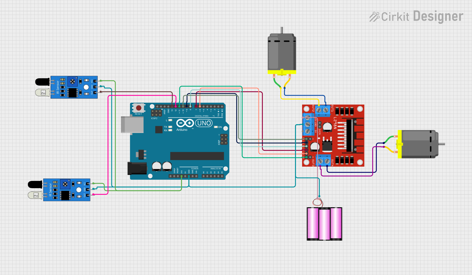
Arduino-Controlled Dual DC Motor Robot with IR Obstacle Detection
Circuit Documentation
Summary
This circuit is designed to control two DC motors using an Arduino UNO microcontroller and an L298N DC motor driver. The circuit also includes two IR sensors for input and a 12V battery as the power source. The Arduino UNO is programmed to interpret signals from the IR sensors and drive the motors accordingly, allowing for forward and backward movement as well as stopping the motors.
Component List
Arduino UNO
- Microcontroller board based on the ATmega328P
- It has 14 digital input/output pins, 6 analog inputs, a 16 MHz quartz crystal, a USB connection, a power jack, an ICSP header, and a reset button.
DC Motor (x2)
- An electric motor that runs on direct current (DC) electricity.
- Typically has two connection pins for power and ground.
L298N DC Motor Driver
- A dual H-bridge motor driver that can drive two DC motors or one stepper motor.
- It has pins for motor connections, power supply, and control signals.
12V Battery
- A power source for the circuit.
- Provides the necessary voltage to drive the motors through the motor driver.
IR Sensor (x2)
- An infrared sensor capable of detecting obstacles or receiving IR signals.
- It has three pins: VCC, GND, and an output signal pin.
Wiring Details
Arduino UNO
3.3Vconnected to VCC of both IR sensors.GNDconnected to the ground of the battery, L298N motor driver, and both IR sensors.D13connected to the output of one IR sensor.D12connected to the output of the other IR sensor.D11connected to ENB on the L298N motor driver.D10connected to ENA on the L298N motor driver.D9connected to IN1 on the L298N motor driver.D8connected to IN2 on the L298N motor driver.D7connected to IN3 on the L298N motor driver.D6connected to IN4 on the L298N motor driver.
DC Motors
- One motor's
pin 1connected to OUT4 andpin 2to OUT3 on the L298N motor driver. - The other motor's
pin 1connected to OUT2 andpin 2to OUT1 on the L298N motor driver.
L298N DC Motor Driver
12Vconnected to the positive terminal of the battery.GNDconnected to the negative terminal of the battery and GND of the Arduino UNO.
12V Battery
+connected to 12V on the L298N motor driver.-connected to GND on the L298N motor driver.
IR Sensors
- Both sensors'
VCCconnected to 3.3V on the Arduino UNO. - Both sensors'
GNDconnected to GND on the Arduino UNO. - One sensor's
outconnected to D13 on the Arduino UNO. - The other sensor's
outconnected to D12 on the Arduino UNO.
Documented Code
// Define motor driver pins
const int motorpin1 = 2; // IN1 forward
const int motorpin2 = 3; // IN2
const int motorpin3 = 4; // IN3 forward
const int motorpin4 = 5; // IN4
const int ENA = 9;
const int ENB = 10;
const int IRL = 7; // Left IR sensor
const int IRR = 6; // Right IR sensor
int R; // Right IR sensor value
int L; // Left IR sensor value

void setup() {
  // Initialize motor driver pins as outputs
  pinMode(motorpin1, OUTPUT);
  pinMode(motorpin2, OUTPUT);
  pinMode(motorpin3, OUTPUT);
  pinMode(motorpin4, OUTPUT);
  pinMode(ENA, OUTPUT);
  pinMode(ENB, OUTPUT);

  // Initialize serial communication at 9600 bits per second
  Serial.begin(9600);
}

void loop() {
  // Print a message to the serial monitor
  Serial.println("Begin testing");

  // Read the IR sensor values
  R = digitalRead(IRR);
  L = digitalRead(IRL);

  // Print the IR sensor values to the serial monitor
  Serial.println(IRR);
  Serial.println(IRL);

  // TODO: Implement the logic based on IR sensor values
  // if (condition) {
  //   // Perform actions based on sensor readings
  // }
}

// Function to move the car forward
void moveForward(int speed) {
  // Motor 1 forward
  analogWrite(ENA, speed);
  digitalWrite(motorpin1, HIGH);
  digitalWrite(motorpin2, LOW);

  // Motor 2 forward
  analogWrite(ENB, speed);
  digitalWrite(motorpin3, HIGH);
  digitalWrite(motorpin4, LOW);

  // Print a message to the serial monitor
  Serial.println("Motor moving forward");
}

// Function to move the car backward
void moveBackward(int speed) {
  // Motor 1 backward
  analogWrite(ENA, speed);
  digitalWrite(motorpin2, HIGH);
  digitalWrite(motorpin1, LOW);

  // Motor 2 backward
  analogWrite(ENB, speed);
  digitalWrite(motorpin4, HIGH);
  digitalWrite(motorpin3, LOW);

  // Print a message to the serial monitor
  Serial.println("Motor moving back");
}

// Function to stop the car
void stop() {
  // Turn off all motors
  digitalWrite(ENA, LOW);
  digitalWrite(ENB, LOW);
  digitalWrite(motorpin1, LOW);
  digitalWrite(motorpin2, LOW);
  digitalWrite(motorpin3, LOW);
  digitalWrite(motorpin4, LOW);

  // Print a message to the serial monitor
  Serial.println("Stopped");
}
Note: The code provided is incomplete and contains placeholders for logic based on IR sensor values. The user should complete the implementation according to the specific requirements of the application.