
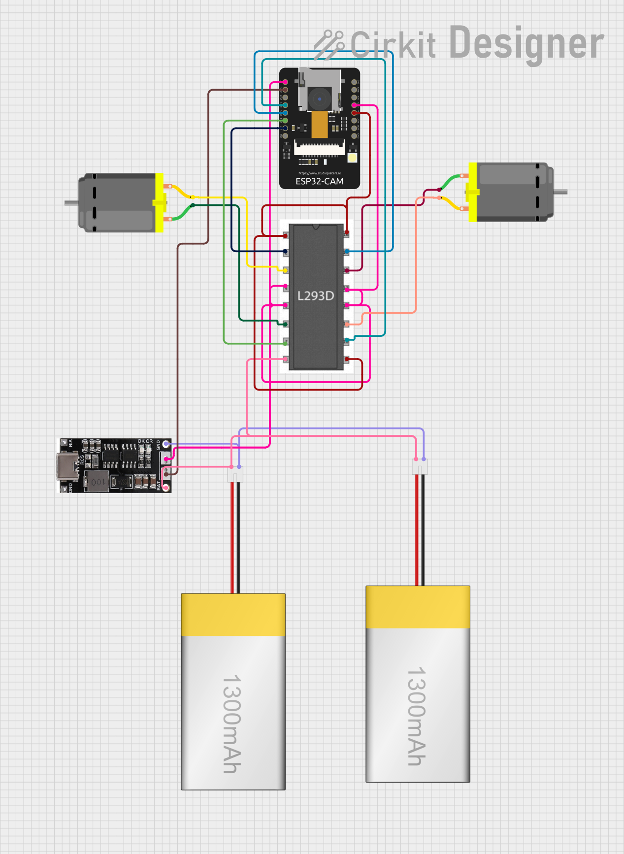
Circuit Documentation
Summary
This circuit is designed to control two DC motors using an ESP32-CAM microcontroller and an L293D motor driver. The circuit is powered by a LiPoly battery and includes a 18650 Lithium Ion Charger for battery management. The ESP32-CAM also includes a camera module for capturing images and streaming video over WiFi.
Component List
ESP32-CAM
- Description: A microcontroller with an integrated camera module.
- Pins: 5V, GND, IO12, IO13, IO15, IO14, IO2, IO4, VOT, VOR, VCC, IO0, IO16, 3V3
DC Motor (Motor 1)
- Description: A DC motor for mechanical movement.
- Pins: pin 1, pin 2
DC Motor (Motor 2)
- Description: A second DC motor for mechanical movement.
- Pins: pin 1, pin 2
L293D
- Description: A motor driver IC used to control the DC motors.
- Pins: Enable 1,2, Input 1, Output 1, GND, Output 2, Input 2, Vcc2, Vcc1, Input 4, Output 4, Output 3, Input 3, Enable 3,4
LiPoly Battery (1300mAh)
- Description: A rechargeable lithium polymer battery.
- Pins: positive, negative
18650 Lithium Ion Charger
- Description: A charger module for 18650 lithium-ion batteries.
- Pins: V IN, GND, OUT, IN, BAT IN, BAT GND
Wiring Details
ESP32-CAM
- 5V: Connected to OUT of 18650 Lithium Ion Charger
- GND: Connected to GND of 18650 Lithium Ion Charger and IN of 18650 Lithium Ion Charger
- IO13: Connected to Input 3 of L293D
- IO15: Connected to Input 4 of L293D
- IO14: Connected to Input 2 of L293D
- IO2: Connected to Input 1 of L293D
- VCC: Connected to Enable 1,2, Enable 3,4, and Vcc1 of L293D
DC Motor (Motor 1)
- pin 1: Connected to Output 4 of L293D
- pin 2: Connected to Output 3 of L293D
DC Motor (Motor 2)
- pin 1: Connected to Output 2 of L293D
- pin 2: Connected to Output 1 of L293D
L293D
- GND: Connected to OUT of 18650 Lithium Ion Charger
- Input 1: Connected to IO2 of ESP32-CAM
- Input 2: Connected to IO14 of ESP32-CAM
- Input 3: Connected to IO13 of ESP32-CAM
- Input 4: Connected to IO15 of ESP32-CAM
- Enable 1,2: Connected to VCC of ESP32-CAM
- Enable 3,4: Connected to VCC of ESP32-CAM
- Vcc1: Connected to VCC of ESP32-CAM
- Vcc2: Connected to BAT IN of 18650 Lithium Ion Charger
LiPoly Battery (1300mAh)
- positive: Connected to BAT IN of 18650 Lithium Ion Charger
- negative: Connected to BAT GND of 18650 Lithium Ion Charger
18650 Lithium Ion Charger
- OUT: Connected to 5V of ESP32-CAM and GND of L293D
- IN: Connected to GND of ESP32-CAM
- BAT IN: Connected to positive of LiPoly Battery
- BAT GND: Connected to negative of LiPoly Battery
Documented Code
#include "esp_camera.h"
#include <WiFi.h>

// WARNING!!! Make sure that you have either selected ESP32 Wrover Module,
//            or another board which has PSRAM enabled
// Adafruit ESP32 Feather

// Select camera model
//#define CAMERA_MODEL_WROVER_KIT
//#define CAMERA_MODEL_M5STACK_PSRAM
#define CAMERA_MODEL_AI_THINKER

const char* ssid = "--------";   //Enter SSID WIFI Name
const char* password = "--------";   //Enter WIFI Password

#if defined(CAMERA_MODEL_WROVER_KIT)
#define PWDN_GPIO_NUM    -1
#define RESET_GPIO_NUM   -1
#define XCLK_GPIO_NUM    21
#define SIOD_GPIO_NUM    26
#define SIOC_GPIO_NUM    27

#define Y9_GPIO_NUM      35
#define Y8_GPIO_NUM      34
#define Y7_GPIO_NUM      39
#define Y6_GPIO_NUM      36
#define Y5_GPIO_NUM      19
#define Y4_GPIO_NUM      18
#define Y3_GPIO_NUM       5
#define Y2_GPIO_NUM       4
#define VSYNC_GPIO_NUM   25
#define HREF_GPIO_NUM    23
#define PCLK_GPIO_NUM    22

#elif defined(CAMERA_MODEL_AI_THINKER)
#define PWDN_GPIO_NUM     32
#define RESET_GPIO_NUM    -1
#define XCLK_GPIO_NUM      0
#define SIOD_GPIO_NUM     26
#define SIOC_GPIO_NUM     27

#define Y9_GPIO_NUM       35
#define Y8_GPIO_NUM       34
#define Y7_GPIO_NUM       39
#define Y6_GPIO_NUM       36
#define Y5_GPIO_NUM       21
#define Y4_GPIO_NUM       19
#define Y3_GPIO_NUM       18
#define Y2_GPIO_NUM        5
#define VSYNC_GPIO_NUM    25
#define HREF_GPIO_NUM     23
#define PCLK_GPIO_NUM     22

#else
#error "Camera model not selected"
#endif

// GPIO Setting
extern int gpLb =  2; // Left 1
extern int gpLf = 14; // Left 2
extern int gpRb = 15; // Right 1
extern int gpRf = 13; // Right 2
extern int gpLed =  4; // Light
extern String WiFiAddr ="";

void startCameraServer();

void setup() {
  Serial.begin(115200);
  Serial.setDebugOutput(true);
  Serial.println();

  pinMode(gpLb, OUTPUT); //Left Backward
  pinMode(gpLf, OUTPUT); //Left Forward
  pinMode(gpRb, OUTPUT); //Right Forward
  pinMode(gpRf, OUTPUT); //Right Backward
  pinMode(gpLed, OUTPUT); //Light

  //initialize
  digitalWrite(gpLb, LOW);
  digitalWrite(gpLf, LOW);
  digitalWrite(gpRb, LOW);
  digitalWrite(gpRf, LOW);
  digitalWrite(gpLed, LOW);

  camera_config_t config;
  config.ledc_channel = LEDC_CHANNEL_0;
  config.ledc_timer = LEDC_TIMER_0;
  config.pin_d0 = Y2_GPIO_NUM;
  config.pin_d1 = Y3_GPIO_NUM;
  config.pin_d2 = Y4_GPIO_NUM;
  config.pin_d3 = Y5_GPIO_NUM;
  config.pin_d4 = Y6_GPIO_NUM;
  config.pin_d5 = Y7_GPIO_NUM;
  config.pin_d6 = Y8_GPIO_NUM;
  config.pin_d7 = Y9_GPIO_NUM;
  config.pin_xclk = XCLK_GPIO_NUM;
  config.pin_pclk = PCLK_GPIO_NUM;
  config.pin_vsync = VSYNC_GPIO_NUM;
  config.pin_href = HREF_GPIO_NUM;
  config.pin_sscb_sda = SIOD_GPIO_NUM;
  config.pin_sscb_scl = SIOC_GPIO_NUM;
  config.pin_pwdn = PWDN_GPIO_NUM;
  config.pin_reset = RESET_GPIO_NUM;
  config.xclk_freq_hz = 20000000;
  config.pixel_format = PIXFORMAT_JPEG;
  //init with high specs to pre-allocate larger buffers
  if(psramFound()){
    config.frame_size = FRAMESIZE_UXGA;
    config.jpeg_quality = 10;
    config.fb_count = 2;
  } else {
    config.frame_size = FRAMESIZE_SVGA;
    config.jpeg_quality = 12;
    config.fb_count = 1;
  }

  // camera init
  esp_err_t err = esp_camera_init(&config);
  if (err != ESP_OK) {
    Serial.printf("Camera init failed with error 0x%x", err);
    return;
  }

  //drop down frame size for higher initial frame rate
  sensor_t * s = esp_camera_sensor_get();
  s->set_framesize(s, FRAMESIZE_CIF);

  WiFi.begin(ssid, password);

  while (WiFi.status() != WL_CONNECTED) {
    delay(500);
    Serial.print(".");
  }
  Serial.println("");
  Serial.println("WiFi connected");

  startCameraServer();

  Serial.print("Camera Ready! Use