
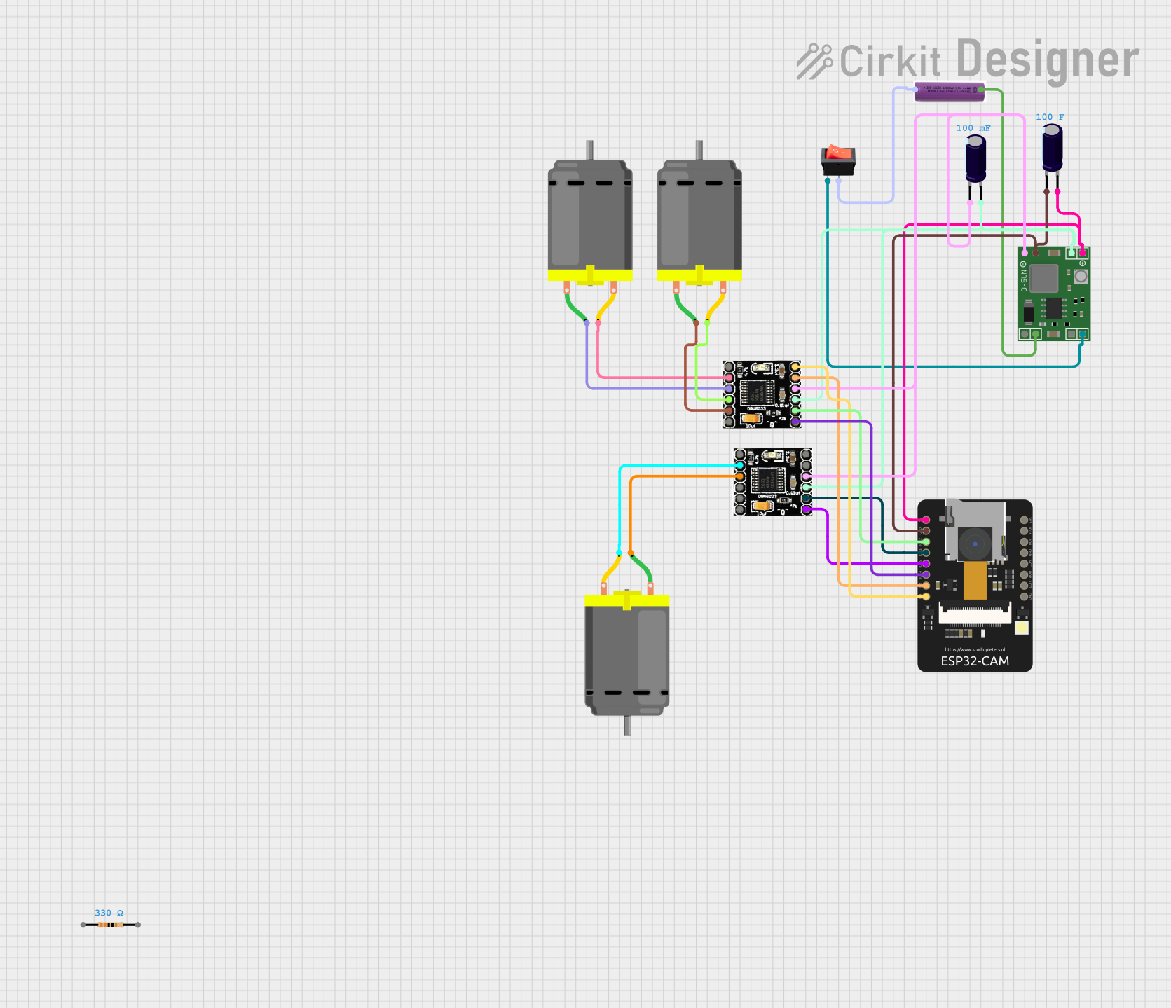
Circuit Documentation
Summary
This document provides a detailed overview of a circuit designed to control a Wi-Fi-enabled car with a camera using an ESP32-CAM microcontroller. The circuit includes various components such as DC motors, a power regulator, a rocker switch, and capacitors. The ESP32-CAM is programmed to control the motors and capture images, which can be viewed and controlled via a web interface.
Component List
ESP32-CAM
- Description: A microcontroller with built-in Wi-Fi and a camera module.
- Pins: 5V, GND, IO12, IO13, IO15, IO14, IO2, IO4, VOT, VOR, VCC, IO0, IO16, 3V3
3.7V Battery
- Description: A rechargeable battery providing power to the circuit.
- Pins: +, -
DC Motor
- Description: A motor used to drive the car.
- Pins: pin 1, pin 2
MP1584EN Power Regulator Board
- Description: A power regulator to step down the voltage.
- Pins: IN -, IN +, OUT +, OUT -
Drv8833
- Description: A dual motor driver.
- Pins: EEP, OUT1, OUT2, OUT3, OUT4, ULT, IN4, IN3, GND, VCC, IN1, IN2
Rocker Switch
- Description: A switch to control the power supply.
- Pins: output, input
Electrolytic Capacitor
- Description: A capacitor used for filtering and stabilization.
- Pins: -, +
- Properties:
- Capacitance: 100 Farads (Instance 1)
- Capacitance: 0.1 Farads (Instance 2)
Resistor
- Description: A resistor used for current limiting.
- Pins: pin1, pin2
- Properties:
- Resistance: 330 Ohms
Wiring Details
ESP32-CAM
- 5V: Connected to the positive terminal of the Electrolytic Capacitor (100 Farads) and the OUT + pin of the MP1584EN Power Regulator Board.
- GND: Connected to the negative terminal of the Electrolytic Capacitor (100 Farads) and the OUT - pin of the MP1584EN Power Regulator Board.
- IO12: Connected to IN1 of the Drv8833 (Instance 1).
- IO13: Connected to IN1 of the Drv8833 (Instance 2).
- IO15: Connected to IN2 of the Drv8833 (Instance 2).
- IO14: Connected to IN2 of the Drv8833 (Instance 1).
- IO2: Connected to IN3 of the Drv8833 (Instance 1).
- IO4: Connected to IN4 of the Drv8833 (Instance 1).
3.7V Battery
- +: Connected to the output pin of the Rocker Switch.
- -: Connected to the IN - pin of the MP1584EN Power Regulator Board.
DC Motor (Instance 1)
- pin 1: Connected to OUT2 of the Drv8833 (Instance 1).
- pin 2: Connected to OUT1 of the Drv8833 (Instance 1).
DC Motor (Instance 2)
- pin 1: Connected to OUT2 of the Drv8833 (Instance 2).
- pin 2: Connected to OUT1 of the Drv8833 (Instance 2).
DC Motor (Instance 3)
- pin 1: Connected to OUT4 of the Drv8833 (Instance 1).
- pin 2: Connected to OUT3 of the Drv8833 (Instance 1).
MP1584EN Power Regulator Board
- IN -: Connected to the negative terminal of the 3.7V Battery.
- IN +: Connected to the input pin of the Rocker Switch.
- OUT +: Connected to the positive terminal of the Electrolytic Capacitor (100 Farads) and the 5V pin of the ESP32-CAM.
- OUT -: Connected to the negative terminal of the Electrolytic Capacitor (100 Farads) and the GND pin of the ESP32-CAM.
Drv8833 (Instance 1)
- IN1: Connected to IO12 of the ESP32-CAM.
- IN2: Connected to IO14 of the ESP32-CAM.
- IN3: Connected to IO2 of the ESP32-CAM.
- IN4: Connected to IO4 of the ESP32-CAM.
- OUT1: Connected to pin 2 of the DC Motor (Instance 1).
- OUT2: Connected to pin 1 of the DC Motor (Instance 1).
- OUT3: Connected to pin 2 of the DC Motor (Instance 3).
- OUT4: Connected to pin 1 of the DC Motor (Instance 3).
- VCC: Connected to the OUT + pin of the MP1584EN Power Regulator Board.
- GND: Connected to the OUT - pin of the MP1584EN Power Regulator Board.
Drv8833 (Instance 2)
- IN1: Connected to IO13 of the ESP32-CAM.
- IN2: Connected to IO15 of the ESP32-CAM.
- OUT1: Connected to pin 2 of the DC Motor (Instance 2).
- OUT2: Connected to pin 1 of the DC Motor (Instance 2).
- VCC: Connected to the OUT + pin of the MP1584EN Power Regulator Board.
- GND: Connected to the OUT - pin of the MP1584EN Power Regulator Board.
Rocker Switch
- output: Connected to the positive terminal of the 3.7V Battery.
- input: Connected to the IN + pin of the MP1584EN Power Regulator Board.
Electrolytic Capacitor (100 Farads)
- +: Connected to the 5V pin of the ESP32-CAM and the OUT + pin of the MP1584EN Power Regulator Board.
- -: Connected to the GND pin of the ESP32-CAM and the OUT - pin of the MP1584EN Power Regulator Board.
Electrolytic Capacitor (0.1 Farads)
- +: Connected to the OUT + pin of the MP1584EN Power Regulator Board.
- -: Connected to the OUT - pin of the MP1584EN Power Regulator Board.
Documented Code
ESP32-CAM Code
#include "esp_camera.h"
#include <Arduino.h>
#include <WiFi.h>
#include <AsyncTCP.h>
#include <ESPAsyncWebServer.h>
#include <iostream>
#include <sstream>

struct MOTOR_PINS
{
  int pinEn;
  int pinIN1;
  int pinIN2;
};

std::vector<MOTOR_PINS> motorPins =
{
  {12, 13, 15},  //RIGHT_MOTOR Pins (EnA, IN1, IN2)
  {12, 14, 2},  //LEFT_MOTOR  Pins (EnB, IN3, IN4)
};
#define LIGHT_PIN 4

#define UP 1
#define DOWN 2
#define LEFT 3
#define RIGHT 4
#define STOP 0

#define RIGHT_MOTOR 0
#define LEFT_MOTOR 1

#define FORWARD 1
#define BACKWARD -1

const int PWMFreq = 1000; /* 1 KHz */
const int PWMResolution = 8;
const int PWMSpeedChannel = 2;
const int PWMLightChannel = 3;

//Camera related constants
#define PWDN_GPIO_NUM     32
#define RESET_GPIO_NUM    -1
#define XCLK_GPIO_NUM      0
#define SIOD_GPIO_NUM     26
#define SIOC_GPIO_NUM     27
#define Y9_GPIO_NUM       35
#define Y8_GPIO_NUM       34
#define Y7_GPIO_NUM       39
#define Y6_GPIO_NUM       36
#define Y5_GPIO_NUM       21
#define Y4_GPIO_NUM       19
#define Y3_GPIO_NUM       18
#define Y2_GPIO_NUM        5
#define VSYNC_GPIO_NUM    25
#define HREF_GPIO_NUM     23
#define PCLK_GPIO_NUM     22

const char* ssid     = "MyWiFiCar";
const char* password = "12345678";

AsyncWebServer server(80);
AsyncWebSocket wsCamera("/Camera");
AsyncWebSocket wsCarInput("/CarInput");
uint32_t cameraClientId = 0;

const char* htmlHomePage PROGMEM = R"HTMLHOMEPAGE(
<!DOCTYPE html>
<html>
  <head>
  <meta name="viewport" content="width=device-width, initial-scale=1,