
Arduino Mega 2560 Based Multi-Channel Thermocouple Temperature Monitoring System
View and Edit Project In Cirkit Designer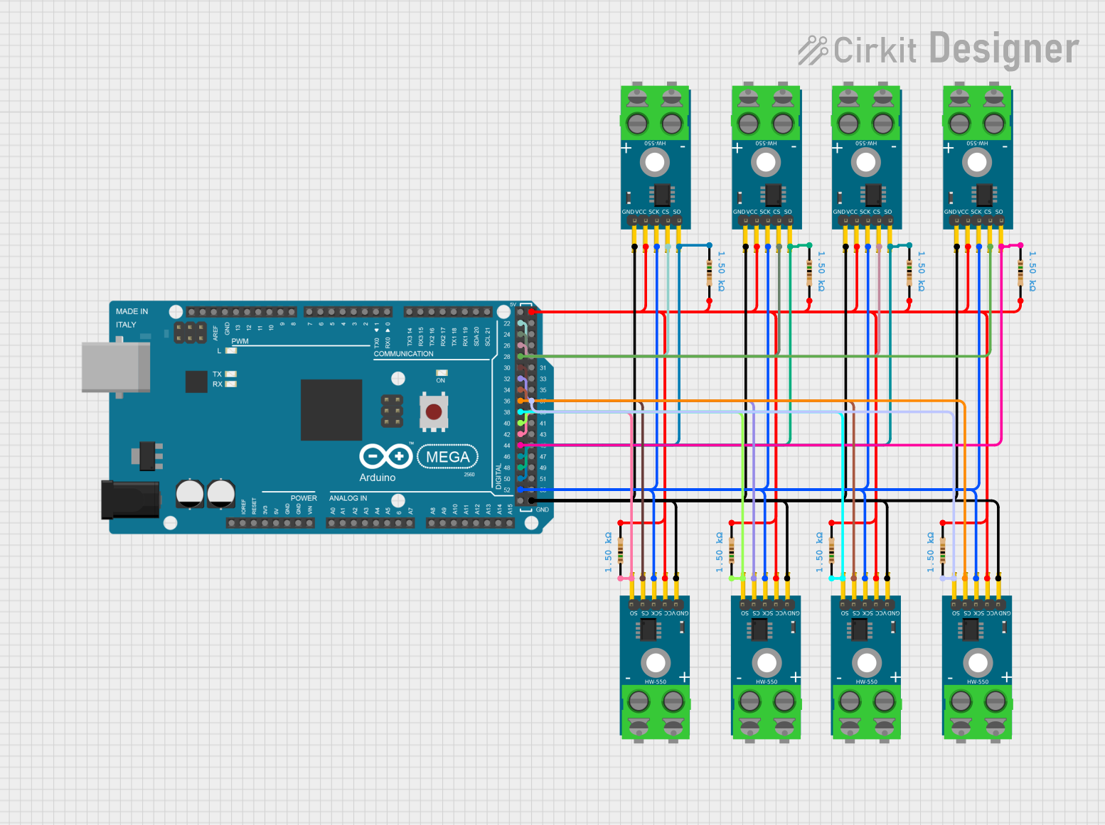
Circuit Documentation
Summary
This circuit integrates an Arduino Mega 2560 microcontroller with multiple MAX6675 thermocouple amplifier modules to measure temperatures. The MAX6675 modules are interfaced with the Arduino Mega 2560 using a shared SPI clock line and individual chip select lines for each module. The temperature data from each thermocouple is read by the Arduino and outputted to the serial monitor. Pull-up resistors are connected to the MISO line of each MAX6675 module to ensure reliable SPI communication.
Component List
Arduino Mega 2560
- Microcontroller board based on the ATmega2560
- It has 54 digital input/output pins, 16 analog inputs, 4 UARTs, a 16 MHz crystal oscillator, a USB connection, a power jack, an ICSP header, and a reset button.
MAX6675 Module (x9)
- Thermocouple-to-digital converter module
- Interfaces with K-type thermocouples
- Provides digital temperature readings with SPI interface
Resistor 1.5k Ohms (x8)
- Passive two-terminal electrical component
- Implements a fixed resistance of 1.5k Ohms
Wiring Details
Arduino Mega 2560
- Digital Pins D22-D38: Connected to the CS (Chip Select) pins of each MAX6675 module.
- Digital Pin D52: Connected to the SCK (Serial Clock) pins of all MAX6675 modules.
- Digital Pins D37, D40, D42, D44, D46, D48, D50: Connected to the SO (Serial Out) pins of the MAX6675 modules through 1.5k Ohm resistors.
- Digital Pin 5V: Provides power to the VCC pins of all MAX6675 modules through 1.5k Ohm resistors.
- Digital Pin GND: Connected to the GND (Ground) pins of all MAX6675 modules.
MAX6675 Module
- SCK: Connected to Digital Pin D52 on the Arduino Mega 2560.
- CS: Connected to individual digital pins D22-D38 on the Arduino Mega 2560 for each module.
- SO: Connected to the Arduino Mega 2560 through a 1.5k Ohm resistor to digital pins D37, D40, D42, D44, D46, D48, D50.
- VCC: Connected to the 5V pin on the Arduino Mega 2560 through a 1.5k Ohm resistor.
- GND: Connected to the GND pin on the Arduino Mega 2560.
Resistor 1.5k Ohms
- One end connected to the SO pin of a MAX6675 module.
- The other end connected to the corresponding digital pin on the Arduino Mega 2560 and to the 5V pin for pull-up configuration.
Documented Code
#include "max6675.h"

// Define the pins for each MAX6675 module
int thermoDO[] = {50, 48, 46, 44, 42, 40, 38, 37};
int thermoCS[] = {22, 24, 26, 28, 30, 32, 34, 36};
int thermoCLK = 52;

// Create an array of MAX6675 objects
MAX6675 thermocouples[8] = {
  MAX6675(thermoCLK, thermoCS[0], thermoDO[0]),
  MAX6675(thermoCLK, thermoCS[1], thermoDO[1]),
  MAX6675(thermoCLK, thermoCS[2], thermoDO[2]),
  MAX6675(thermoCLK, thermoCS[3], thermoDO[3]),
  MAX6675(thermoCLK, thermoCS[4], thermoDO[4]),
  MAX6675(thermoCLK, thermoCS[5], thermoDO[5]),
  MAX6675(thermoCLK, thermoCS[6], thermoDO[6]),
  MAX6675(thermoCLK, thermoCS[7], thermoDO[7])
};

void setup() {
  Serial.begin(9600);
  Serial.println("MAX6675 test");
  // A short delay before starting the main loop
  delay(500);
}

void loop() {
  // Loop through each thermocouple and read temperatures
  for (int i = 0; i < 8; i++) {
    Serial.print("Thermocouple ");
    Serial.print(i + 1);
    Serial.print(": ");
    // Read the temperature in Celsius and print it
    Serial.print(thermocouples[i].readCelsius());
    Serial.println(" C");
  }
  // Wait for a second before reading temperatures again
  delay(1000);
}
This code initializes an array of MAX6675 objects, each representing a thermocouple module connected to the Arduino. It configures the SPI communication pins and reads the temperature from each thermocouple in a loop, printing the results to the serial monitor.