Arduino UNO-Based Environmental Monitoring System with Temperature and Gas Sensors
Circuit Documentation
Summary
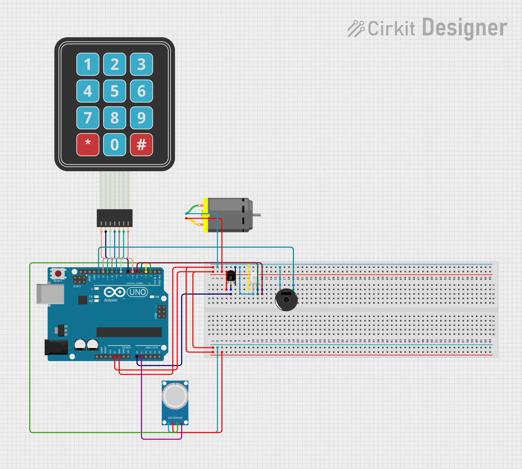
This circuit is designed to monitor temperature and gas levels using an Arduino UNO microcontroller. It includes a temperature sensor (LM35), a gas sensor (MQ-4), an RGB LED, a membrane matrix keypad, a piezo buzzer, and a DC motor. The Arduino UNO reads data from the sensors and controls the RGB LED, buzzer, and motor based on the sensor readings.
Component List
Arduino UNO
- Description: Microcontroller board based on the ATmega328P.
- Pins: UNUSED, IOREF, Reset, 3.3V, 5V, GND, Vin, A0, A1, A2, A3, A4, A5, SCL, SDA, AREF, D13, D12, D11, D10, D9, D8, D7, D6, D5, D4, D3, D2, D1, D0
Temperature Sensor (LM35)
- Description: Analog temperature sensor.
- Pins: +Vs, Vout, GND
MQ-4
- Description: Gas sensor for detecting methane (CH4).
- Pins: A0, D0, GND, VCC
RGB LED (Wokwi compatible)
- Description: RGB LED with common cathode.
- Pins: R, COM, G, B
Membrane Matrix Keypad
- Description: 4x3 matrix keypad.
- Pins: Row 1, Row 2, Row 3, Row 4, Column 1, Column 2, Column 3
Piezo Buzzer
- Description: Simple piezoelectric buzzer.
- Pins: pin 1, pin 2
DC Motor
- Description: Standard DC motor.
- Pins: pin 1, pin 2
Wiring Details
Arduino UNO
- 5V: Connected to +Vs of Temperature Sensor (LM35), pin 2 of DC Motor, and VCC of MQ-4.
- A0: Connected to Vout of Temperature Sensor (LM35).
- A1: Connected to A0 of MQ-4.
- D3: Connected to R of RGB LED.
- D4: Connected to G of RGB LED.
- D5: Connected to B of RGB LED.
- D6: Connected to Row 1 of Membrane Matrix Keypad.
- D7: Connected to Row 2 of Membrane Matrix Keypad.
- D8: Connected to Row 3 of Membrane Matrix Keypad.
- D9: Connected to Row 4 of Membrane Matrix Keypad.
- D10: Connected to Column 1 of Membrane Matrix Keypad.
- D11: Connected to Column 2 of Membrane Matrix Keypad.
- D12: Connected to Column 3 of Membrane Matrix Keypad.
- D13: Connected to pin 1 of Piezo Buzzer.
- GND: Connected to COM of RGB LED, GND of Temperature Sensor (LM35), pin 1 of DC Motor, pin 2 of Piezo Buzzer, and GND of MQ-4.
- D2: Connected to D0 of MQ-4.
Temperature Sensor (LM35)
- +Vs: Connected to 5V of Arduino UNO.
- Vout: Connected to A0 of Arduino UNO.
- GND: Connected to GND of Arduino UNO.
MQ-4
- A0: Connected to A1 of Arduino UNO.
- D0: Connected to D2 of Arduino UNO.
- GND: Connected to GND of Arduino UNO.
- VCC: Connected to 5V of Arduino UNO.
RGB LED (Wokwi compatible)
- R: Connected to D3 of Arduino UNO.
- COM: Connected to GND of Arduino UNO.
- G: Connected to D4 of Arduino UNO.
- B: Connected to D5 of Arduino UNO.
Membrane Matrix Keypad
- Row 1: Connected to D6 of Arduino UNO.
- Row 2: Connected to D7 of Arduino UNO.
- Row 3: Connected to D8 of Arduino UNO.
- Row 4: Connected to D9 of Arduino UNO.
- Column 1: Connected to D10 of Arduino UNO.
- Column 2: Connected to D11 of Arduino UNO.
- Column 3: Connected to D12 of Arduino UNO.
Piezo Buzzer
- pin 1: Connected to D13 of Arduino UNO.
- pin 2: Connected to GND of Arduino UNO.
DC Motor
- pin 1: Connected to GND of Arduino UNO.
- pin 2: Connected to 5V of Arduino UNO.
Documented Code
#include <Keypad.h>

const int tempPin = A0;
const int gasPin = A1;
const int buzzerPin = 13;
const int fanPin = 12;

void setup() {
    pinMode(buzzerPin, OUTPUT);
    pinMode(fanPin, OUTPUT);
    Serial.begin(9600);
}

void loop() {
    int temp = analogRead(tempPin) * (5.0 / 1023.0) * 100;
    int gas = analogRead(gasPin);

    Serial.print("Temperature: ");
    Serial.println(temp);
    Serial.print("Gas Level: ");
    Serial.println(gas);

    if (temp > 30) {
        digitalWrite(fanPin, HIGH);
    } else {
        digitalWrite(fanPin, LOW);
    }

    if (gas > 400) {
        digitalWrite(buzzerPin, HIGH);
    } else {
        digitalWrite(buzzerPin, LOW);
    }

    delay(1000);
}
This code reads the temperature and gas levels from the sensors and controls the fan and buzzer based on the readings. The temperature is read from the LM35 sensor connected to pin A0, and the gas level is read from the MQ-4 sensor connected to pin A1. If the temperature exceeds 30°C, the fan is turned on. If the gas level exceeds a threshold of 400, the buzzer is activated. The readings are also printed to the serial monitor.