
ESP32-Based Smart Fan Control System with Gas and Temperature Monitoring
View and Edit Project In Cirkit Designer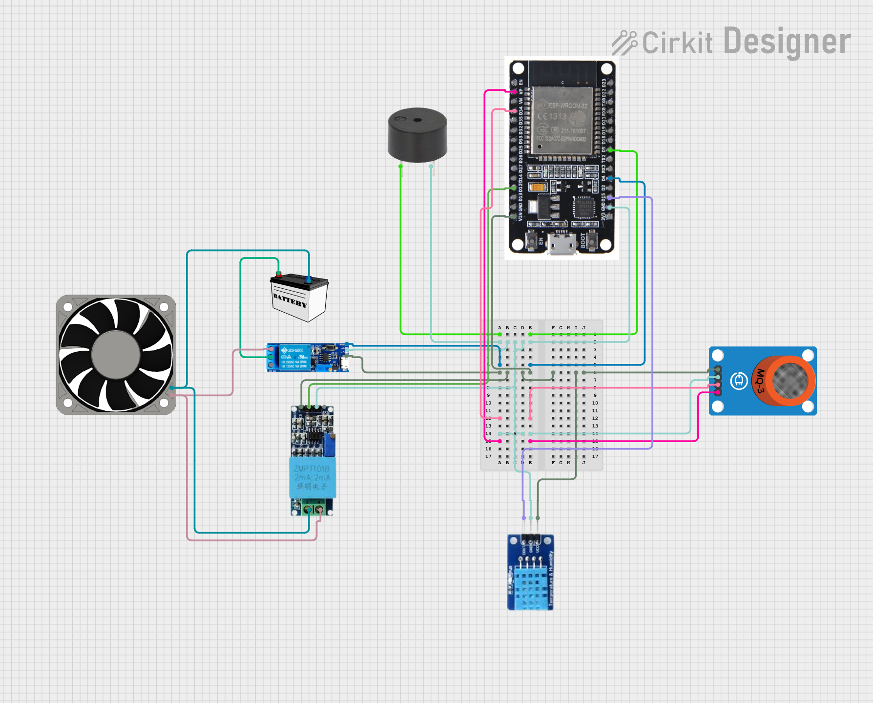
Circuit Documentation
Summary
This document provides a detailed overview of a circuit that includes various components such as an ESP32 microcontroller, sensors, a relay module, a fan, and a buzzer. The circuit is designed to monitor environmental conditions and control a fan based on sensor inputs. The ESP32 microcontroller serves as the central control unit, interfacing with the sensors and actuators.
Component List
40 Fan 12v
- Description: A 12V DC fan.
- Pins: +12V, -12V
Relay module 5v-30v
- Description: A relay module capable of switching voltages between 5V and 30V.
- Pins: common contact, normally open, normally closed, trigger, V-, V+
ESP32
- Description: A versatile microcontroller with Wi-Fi and Bluetooth capabilities.
- Pins: EN, VP, VN, D34, D35, D32, D33, D25, D26, D27, D14, D12, D13, GND, VIN, 3V3, D15, D2, D4, RX2, TX2, D5, D18, D19, D21, RX0, TX0, D22, D23, BOOT
MQ-3 Breakout
- Description: An alcohol sensor module.
- Pins: VCC, GND, DO, AO
DHT11
- Description: A temperature and humidity sensor.
- Pins: DATA, GND, VCC
Buzzer
- Description: An electronic buzzer.
- Pins: PIN, GND
Voltage Sensor
- Description: A sensor to measure voltage.
- Pins: Ground, Phase, Vcc, Out, Gnd
12V Battery (Small Size)
- Description: A small-sized 12V battery.
- Pins: VCC, GND
Wiring Details
40 Fan 12v
- +12V is connected to the normally open pin of the Relay module 5v-30v and the Phase pin of the Voltage Sensor.
- -12V is connected to the Ground pin of the Voltage Sensor and the GND pin of the 12V Battery (Small Size).
Relay module 5v-30v
- common contact is connected to the VCC pin of the 12V Battery (Small Size).
- normally open is connected to the +12V pin of the 40 Fan 12v and the Phase pin of the Voltage Sensor.
- trigger is connected to the D4 pin of the ESP32.
- V- is connected to the GND pin of the ESP32, GND pin of the DHT11, GND pin of the buzzer, GND pin of the MQ-3 Breakout, and the Gnd pin of the Voltage Sensor.
- V+ is connected to the VIN pin of the ESP32, VCC pin of the DHT11, Vcc pin of the Voltage Sensor, and the VCC pin of the MQ-3 Breakout.
ESP32
- D5 is connected to the PIN of the buzzer.
- GND is connected to the GND pin of the DHT11, V- pin of the Relay module 5v-30v, Gnd pin of the Voltage Sensor, GND pin of the buzzer, and the GND pin of the MQ-3 Breakout.
- D4 is connected to the trigger pin of the Relay module 5v-30v.
- VIN is connected to the VCC pin of the DHT11, V+ pin of the Relay module 5v-30v, Vcc pin of the Voltage Sensor, and the VCC pin of the MQ-3 Breakout.
- D34 is connected to the DO pin of the MQ-3 Breakout.
- VP is connected to the AO pin of the MQ-3 Breakout.
- D12 is connected to the Out pin of the Voltage Sensor.
- D15 is connected to the DATA pin of the DHT11.
MQ-3 Breakout
- VCC is connected to the VIN pin of the ESP32, VCC pin of the DHT11, V+ pin of the Relay module 5v-30v, and the Vcc pin of the Voltage Sensor.
- GND is connected to the GND pin of the ESP32, GND pin of the DHT11, V- pin of the Relay module 5v-30v, Gnd pin of the Voltage Sensor, and the GND pin of the buzzer.
- DO is connected to the D34 pin of the ESP32.
- AO is connected to the VP pin of the ESP32.
DHT11
- DATA is connected to the D15 pin of the ESP32.
- GND is connected to the GND pin of the ESP32, V- pin of the Relay module 5v-30v, Gnd pin of the Voltage Sensor, GND pin of the buzzer, and the GND pin of the MQ-3 Breakout.
- VCC is connected to the VIN pin of the ESP32, V+ pin of the Relay module 5v-30v, Vcc pin of the Voltage Sensor, and the VCC pin of the MQ-3 Breakout.
Buzzer
- PIN is connected to the D5 pin of the ESP32.
- GND is connected to the GND pin of the ESP32, GND pin of the DHT11, V- pin of the Relay module 5v-30v, Gnd pin of the Voltage Sensor, and the GND pin of the MQ-3 Breakout.
Voltage Sensor
- Ground is connected to the -12V pin of the 40 Fan 12v and the GND pin of the 12V Battery (Small Size).
- Phase is connected to the +12V pin of the 40 Fan 12v and the normally open pin of the Relay module 5v-30v.
- Vcc is connected to the VIN pin of the ESP32, VCC pin of the DHT11, V+ pin of the Relay module 5v-30v, and the VCC pin of the MQ-3 Breakout.
- Out is connected to the D12 pin of the ESP32.
- Gnd is connected to the GND pin of the ESP32, GND pin of the DHT11, V- pin of the Relay module 5v-30v, GND pin of the buzzer, and the GND pin of the MQ-3 Breakout.
12V Battery (Small Size)
- VCC is connected to the common contact pin of the Relay module 5v-30v.
- GND is connected to the Ground pin of the Voltage Sensor and the -12V pin of the 40 Fan 12v.
Code
No code is provided for this circuit.