Cirkit Designer
Your all-in-one circuit design IDE
Home /
Project Documentation
Arduino UNO-Based RFID Access Control System with Pushbutton Interface and I2C LCD Display
Circuit Documentation
Summary
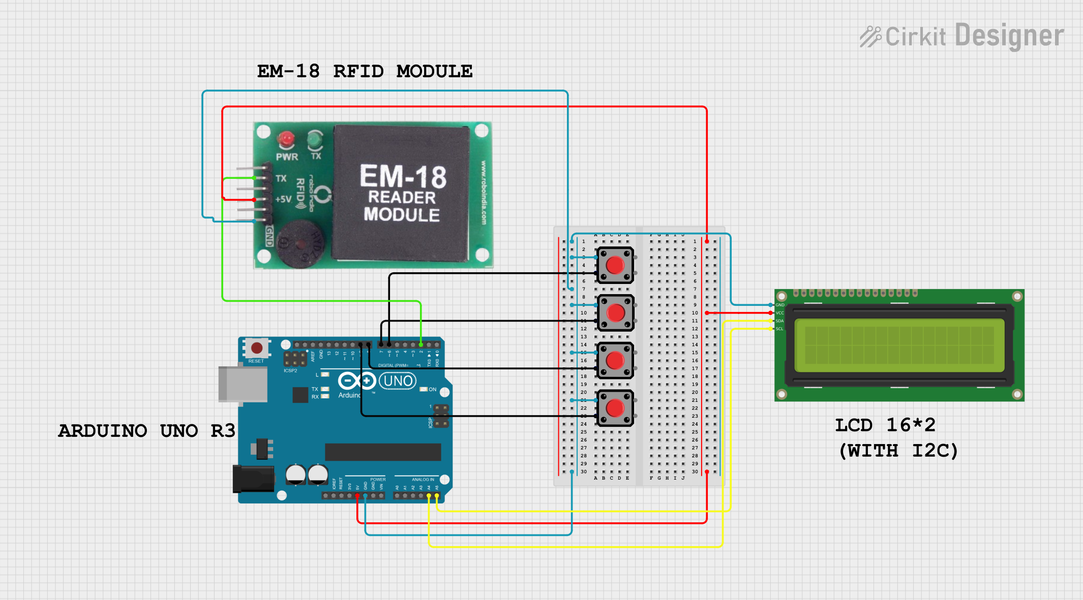
This circuit involves an Arduino UNO microcontroller interfacing with multiple pushbuttons, an RFID module, and a 16x2 I2C LCD display. The pushbuttons are used as input devices, the RFID module is used for reading RFID tags, and the LCD display is used for visual output. The Arduino UNO serves as the central controller, processing inputs and controlling outputs.
Component List
Pushbutton
- Description: A simple pushbutton switch.
- Pins: Pin 1, Pin 2, Pin 3, Pin 4
Arduino UNO
- Description: A microcontroller board based on the ATmega328P.
- Pins: UNUSED, IOREF, Reset, 3.3V, 5V, GND, Vin, A0, A1, A2, A3, A4, A5, SCL, SDA, AREF, D13, D12, D11, D10, D9, D8, D7, D6, D5, D4, D3, D2, D1, D0
EM-18 RFID Module
- Description: An RFID reader module.
- Pins: TX, VCC, GND
16x2 I2C LCD
- Description: A 16x2 character LCD display with I2C interface.
- Pins: GND, VCC, SDA, SCL
Comment
- Description: Placeholder for comments in the circuit.
- Pins: None
Wiring Details
Pushbutton 1
- Pin 2: Connected to GND
- Pin 3: Connected to Arduino UNO D6
Pushbutton 2
- Pin 2: Connected to GND
- Pin 1: Connected to Arduino UNO D7
Pushbutton 3
- Pin 2: Connected to GND
- Pin 3: Connected to Arduino UNO D8
Pushbutton 4
- Pin 2: Connected to GND
- Pin 3: Connected to Arduino UNO D9
Arduino UNO
- GND: Connected to GND of Pushbutton 1, Pushbutton 2, Pushbutton 3, Pushbutton 4, 16x2 I2C LCD, and EM-18 RFID Module
- D6: Connected to Pin 3 of Pushbutton 1
- D7: Connected to Pin 1 of Pushbutton 2
- D8: Connected to Pin 3 of Pushbutton 3
- D9: Connected to Pin 3 of Pushbutton 4
- 5V: Connected to VCC of 16x2 I2C LCD and EM-18 RFID Module
- A4: Connected to SDA of 16x2 I2C LCD
- A5: Connected to SCL of 16x2 I2C LCD
- D2: Connected to TX of EM-18 RFID Module
EM-18 RFID Module
- TX: Connected to Arduino UNO D2
- VCC: Connected to Arduino UNO 5V
- GND: Connected to GND
16x2 I2C LCD
- GND: Connected to GND
- VCC: Connected to Arduino UNO 5V
- SDA: Connected to Arduino UNO A4
- SCL: Connected to Arduino UNO A5
Code Documentation
Arduino UNO Code
void setup() {
  // put your setup code here, to run once:

}

void loop() {
  // put your main code here, to run repeatedly:

}
This code is a basic template for the Arduino UNO. The setup() function is where you initialize your components and settings, and the loop() function is where the main logic of your program runs repeatedly.
Additional Documentation
This section is reserved for any additional documentation or comments related to the code or circuit.