
ESP32-Based Carbon Monoxide Detector with OLED Display and Alert System
View and Edit Project In Cirkit Designer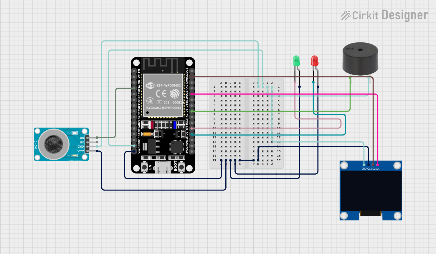
Circuit Documentation
Summary
This circuit integrates various components to perform a set of functions centered around the ESP32 microcontroller. The ESP32 serves as the central processing unit, interfacing with an OLED display, a carbon monoxide gas sensor (MQ-7), a buzzer, and two LEDs (red and green). The circuit is designed to monitor the environment for carbon monoxide levels, provide visual feedback through the LEDs, audible alerts through the buzzer, and display data on the OLED screen.
Component List
ESP32 (30 pin)
- Description: A microcontroller with Wi-Fi and Bluetooth capabilities, featuring a wide range of GPIO pins.
- Purpose: Acts as the central processing unit for the circuit, managing sensor data, controlling LEDs, driving the display, and handling communication.
LED: Two Pin (red)
- Description: A basic red LED for visual indication.
- Purpose: Provides visual feedback, possibly indicating a warning or alert status.
LED: Two Pin (green)
- Description: A basic green LED for visual indication.
- Purpose: Provides visual feedback, possibly indicating normal operation or safe status.
128x64 OLED Display (I2C IIC SPI Serial)
- Description: A small display capable of showing text and graphics.
- Purpose: Displays information such as sensor readings and system status.
MQ-7 SENSOR CARBON MONOXIDE GAS
- Description: A sensor for detecting the presence of carbon monoxide gas in the air.
- Purpose: Monitors environmental carbon monoxide levels for safety and alerting purposes.
Buzzer
- Description: An audible signaling device.
- Purpose: Emits an audible alert in response to certain conditions, such as high carbon monoxide levels.
Wiring Details
ESP32 (30 pin)
- GND: Connected to the ground pins of the buzzer, OLED display, MQ-7 sensor.
- Vin: Powers the OLED display, green LED, red LED, and MQ-7 sensor.
- D34: Receives digital input from the MQ-7 sensor's D0 pin.
- D22 (SCL): Connected to the SCL pin of the OLED display for I2C communication.
- D21 (SDA): Connected to the SDA pin of the OLED display for I2C communication.
- D5: Connected to the buzzer's PIN for control.
- D4: Connected to the green LED's cathode to control its state.
- D2: Connected to the red LED's cathode to control its state.
LED: Two Pin (red)
- Cathode: Connected to the ESP32's D2 pin.
- Anode: Connected to the ESP32's Vin (power).
LED: Two Pin (green)
- Cathode: Connected to the ESP32's D4 pin.
- Anode: Connected to the ESP32's Vin (power).
128x64 OLED Display (I2C IIC SPI Serial)
- GND: Connected to the ESP32's GND pin.
- SDA: Connected to the ESP32's D21 pin for I2C communication.
- SCL: Connected to the ESP32's D22 pin for I2C communication.
- VCC: Connected to the ESP32's Vin (power).
MQ-7 SENSOR CARBON MONOXIDE GAS
- VCC: Connected to the ESP32's Vin (power).
- GND: Connected to the ESP32's GND pin.
- A0: Analog output (not connected in this circuit).
- D0: Digital output connected to the ESP32's D34 pin.
Buzzer
- PIN: Connected to the ESP32's D5 pin for control.
- GND: Connected to the ESP32's GND pin.
Documented Code
No code was provided for the microcontroller. The expected functionality based on the wiring would include reading the digital output from the MQ-7 sensor, controlling the state of the LEDs and buzzer, and updating the OLED display with relevant information. The code would likely involve initializing the I2C communication for the OLED display, setting up GPIO pins for the LEDs and buzzer, and implementing logic to handle sensor readings and trigger alerts.