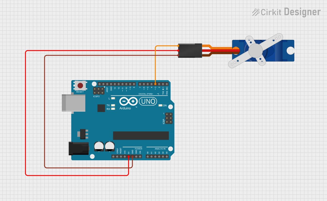
Arduino UNO Controlled Servo Motor

Circuit Documentation
Summary of the Circuit
This circuit consists of an Arduino UNO microcontroller board interfaced with a Tower Pro SG90 servo motor. The Arduino UNO provides control signals to the servo motor, as well as power and ground connections. The servo motor is controlled through one of the digital pins of the Arduino UNO, which sends PWM (Pulse Width Modulation) signals to set the position of the servo motor.
Component List
Arduino UNO
- Description: A microcontroller board based on the ATmega328P.
- Pins: UNUSED, IOREF, Reset, 3.3V, 5V, GND, Vin, A0-A5, SCL, SDA, AREF, D0-D13.
- Purpose: Acts as the main controller for the circuit, providing logic and power to the servo motor.
Tower Pro SG90 Servo
- Description: A small and lightweight servo motor suitable for beginner projects.
- Pins: Signal, +5V, GND.
- Purpose: Receives control signals from the Arduino UNO to adjust its position accordingly.
Wiring Details
Arduino UNO
- 5V: Provides power to the servo motor.
- GND: Common ground with the servo motor.
- D3: Sends PWM control signals to the servo motor.
Tower Pro SG90 Servo
- Signal: Receives PWM control signals from the Arduino UNO's D3 pin.
- +5V: Connected to the 5V output from the Arduino UNO.
- GND: Shares a common ground with the Arduino UNO.
Documented Code
The following code is intended to run on the Arduino UNO microcontroller to control the Tower Pro SG90 servo motor. The code is written in Arduino's programming language (based on C/C++) and should be uploaded to the Arduino UNO using the Arduino IDE.
void setup() {
  // put your setup code here, to run once:

}

void loop() {
  // put your main code here, to run repeatedly:

}
File Name: sketch.ino
This code template is a starting point for further development. The setup() function is called once when the microcontroller is powered on or reset. It is typically used to initialize variables, pin modes, start using libraries, etc. The loop() function is called repeatedly and contains the main logic of the code. To control the servo motor, one would typically configure a PWM output on pin D3 and then use this to send signals to the servo to set its position.