
Circuit Documentation
Summary
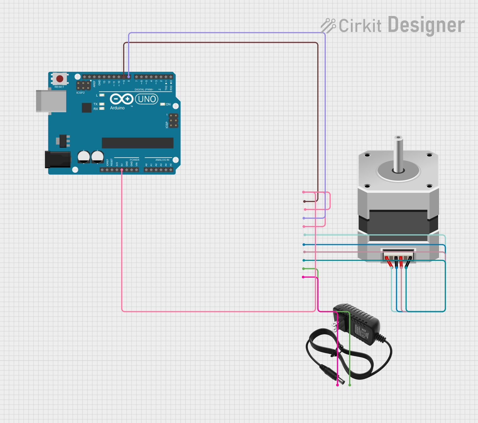
This circuit is designed to control a bipolar stepper motor using an Arduino UNO and a stepper driver. The Arduino UNO sends control signals to the stepper driver, which in turn drives the stepper motor. A 12V power supply is used to power the stepper driver.
Component List
Arduino UNO
- Description: A microcontroller board based on the ATmega328P.
- Pins: UNUSED, IOREF, Reset, 3.3V, 5V, GND, Vin, A0, A1, A2, A3, A4, A5, SCL, SDA, AREF, D13, D12, D11, D10, D9, D8, D7, D6, D5, D4, D3, D2, D1, D0
Stepper Driver
- Description: A driver module for controlling a stepper motor.
- Pins: ENA -, ENA +, DIR -, DIR+, PUL -, PUL +, B-, B+, A-, A+, GND, VCC
Stepper Motor (Bipolar)
- Description: A bipolar stepper motor with four pins.
- Pins: D, B, C, A
12V Power Supply
- Description: A power supply providing 12V DC.
- Pins: +, -
Wiring Details
Arduino UNO
- 5V to Stepper Driver ENA +, DIR+, PUL +
- D9 to Stepper Driver DIR -
- D8 to Stepper Driver PUL -
Stepper Driver
- ENA + to Arduino UNO 5V
- DIR+ to Arduino UNO 5V
- PUL + to Arduino UNO 5V
- DIR - to Arduino UNO D9
- PUL - to Arduino UNO D8
- B- to Stepper Motor (Bipolar) A
- B+ to Stepper Motor (Bipolar) C
- A- to Stepper Motor (Bipolar) B
- A+ to Stepper Motor (Bipolar) D
- GND to 12V Power Supply -
- VCC to 12V Power Supply +
Stepper Motor (Bipolar)
- A to Stepper Driver B-
- C to Stepper Driver B+
- B to Stepper Driver A-
- D to Stepper Driver A+
12V Power Supply
- + to Stepper Driver VCC
- - to Stepper Driver GND
Code Documentation
/*
 * Arduino Sketch to control a stepper motor using a stepper driver.
 * The motor runs for 10 seconds and then stops for 10 seconds in a loop.
 * Connections:
 * - Arduino D9 to Stepper Driver DIR-
 * - Arduino D8 to Stepper Driver PUL-
 * - Arduino 5V to Stepper Driver ENA+, DIR+, PUL+
 * - 12V Power Supply to Stepper Driver VCC, GND
 */

const int dirPin = 9; // Direction pin
const int stepPin = 8; // Step pin
const int stepsPerRevolution = 200; // Steps per revolution for the motor

void setup() {
  pinMode(dirPin, OUTPUT);
  pinMode(stepPin, OUTPUT);
  digitalWrite(dirPin, HIGH); // Set motor direction
}

void loop() {
  // Run the motor for 10 seconds
  for (int i = 0; i < stepsPerRevolution * 10; i++) {
    digitalWrite(stepPin, HIGH);
    delayMicroseconds(1000); // Adjust delay for speed control
    digitalWrite(stepPin, LOW);
    delayMicroseconds(1000);
  }
  delay(10000); // Wait for 10 seconds

  // Stop the motor for 10 seconds
  delay(10000);
}
File Name: sketch.ino