
Circuit Documentation
Summary of the Circuit
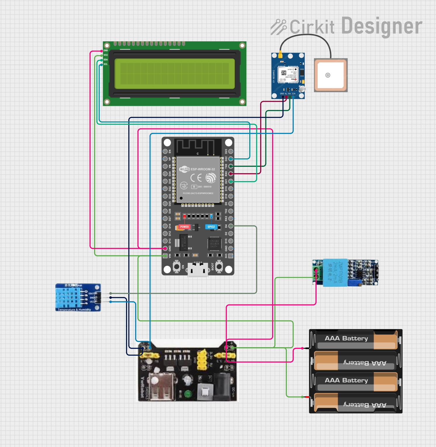
This circuit integrates various components to perform multiple functions. It features an ESP32 DEVKIT V1 microcontroller as the central processing unit, interfacing with a DHT11 temperature and humidity sensor, a GPS NEO 6M module for location tracking, a voltage sensor for monitoring electrical parameters, and an I2C LCD 16x2 screen for data display. The circuit is powered by a 4 x AAA battery mount through an MB102 Breadboard Power Supply Module that provides regulated 3.3V and 5V outputs. The ESP32 DEVKIT V1 manages data acquisition, processing, and display, while also communicating with the GPS module.
Component List
ESP 32 DEVKIT V1 (30 pins)
- Microcontroller with WiFi and Bluetooth capabilities.
- 30 GPIO pins for interfacing with various peripherals.
DHT11
- A basic, ultra low-cost digital temperature and humidity sensor.
- It uses a capacitive humidity sensor and a thermistor to measure the surrounding air.
MB102 Breadboard Power Supply Module 3.3V/5V
- Provides 3.3V and 5V power supply outputs, suitable for breadboard power supply needs.
GPS NEO 6M
- A GPS module that provides location data.
- It communicates with the microcontroller via serial communication.
4 x AAA Battery Mount
- A battery holder for four AAA batteries.
- Provides power to the circuit.
Voltage Sensor
- Measures the voltage between two points.
- Useful for battery monitoring or voltage sensing in the circuit.
I2C LCD 16x2 Screen
- An alphanumeric LCD display with 16 characters by 2 lines.
- Uses I2C communication for displaying data.
Wiring Details
ESP 32 DEVKIT V1 (30 pins)
- GND connected to the common ground rail.
- VIN connected to the 5V output from the MB102 power supply module.
- D4 connected to the DATA pin of the DHT11 sensor.
- D21 (SDA) and D22 (SCL) connected to the SDA and SCL pins of the I2C LCD screen, respectively.
- RX0 connected to the TX pin of the GPS NEO 6M module.
- TX0 connected to the RX pin of the GPS NEO 6M module.
DHT11
- DATA connected to D4 on the ESP32.
- GND connected to the common ground rail.
- VCC connected to the 3.3V output from the MB102 power supply module.
MB102 Breadboard Power Supply Module 3.3V/5V
- GND connected to the common ground rail.
- 3.3V output connected to the VCC pin of the GPS NEO 6M and the VCC pin of the DHT11.
- 5V output connected to the VIN pin of the ESP32 and the VCC (5V) pin of the I2C LCD screen.
GPS NEO 6M
- VCC connected to the 3.3V output from the MB102 power supply module.
- RX connected to the TX0 pin on the ESP32.
- TX connected to the RX0 pin on the ESP32.
- GND connected to the common ground rail.
4 x AAA Battery Mount
- + connected to the 5V input of the MB102 power supply module.
- - connected to the common ground rail.
Voltage Sensor
- Ground connected to the common ground rail.
- Phase connected to the VIN pin of the ESP32.
- Vcc not connected in the provided net list.
- Out not connected in the provided net list.
- Gnd connected to the common ground rail.
I2C LCD 16x2 Screen
- SDA connected to D21 on the ESP32.
- SCL connected to D22 on the ESP32.
- VCC (5V) connected to the 5V output from the MB102 power supply module.
- GND connected to the common ground rail.
Documented Code
Since no code was provided in the input, this section is not applicable. Normally, this section would include the embedded code for the microcontroller, with comments explaining the functionality of each part of the code.