
ESP32-Based IoT Indoor Air Quality Monitoring System with OLED Display and RGB LED
View and Edit Project In Cirkit Designer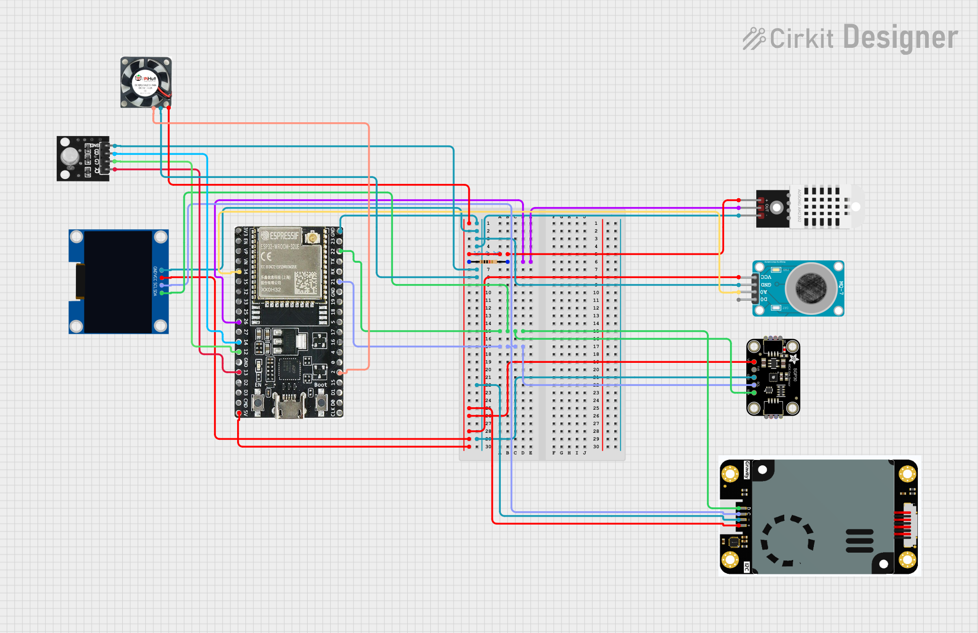
IoT Indoor Air Quality Monitoring Circuit Documentation
Summary
This document provides a detailed overview of an IoT Indoor Air Quality Monitoring system. The system measures temperature, humidity, carbon monoxide (CO), and PM2.5 levels using various sensors and displays the readings on a 128x64 OLED display. The ESP32 microcontroller is used to read sensor data and update the display. Additionally, the data is sent to the serial monitor. The RGB LED and fan are controlled based on air quality: green LED and fan off for normal air quality, red LED and fan on for poor air quality.
Component List
ESP32-WROOM-32UE
- Description: Microcontroller
- Pins: 3v3, EN, VP, VN, 34, 35, 32, 33, 25, 26, 27, 14, 12, GND, 13, D2, D3, 5V, 23, 22, TX, RX, 21, 19, 18, 5, 17, 16, 4, 0, 2, 15, D1, D0, CKL
MQ-7 SENSOR CARBON MONOXIDE GAS
- Description: CO Gas Sensor
- Pins: VCC, GND, A0, D0
128x64 OLED Display (I2C IIC SPI Serial)
- Description: OLED Display
- Pins: GND, SDA, SCL, VCC
DHT22
- Description: Temperature and Humidity Sensor
- Pins: +, Out, -
Resistor
- Description: Resistor
- Pins: pin1, pin2
- Properties: 10k Ohms
Adafruit SGP30
- Description: Air Quality Sensor
- Pins: VCC, 3.3V, GND, SCL, SDA
Gravity : PM2.5 Air Quality Sensor
- Description: PM2.5 Air Quality Sensor
- Pins: SDA/D, SCL/C, GND/-, VCC/+
RGB Led module
- Description: RGB LED
- Pins: +VCC Red, +VCC Green, +VCC Blue, GND
PWM fan
- Description: Fan
- Pins: VCC, GND, PWM
Wiring Details
ESP32-WROOM-32UE
5V connected to:
- VCC of DHT22
- VCC of PWM fan
- VCC/+ of Gravity PM2.5 Air Quality Sensor
- VCC of Adafruit SGP30
- VCC of MQ-7 SENSOR CARBON MONOXIDE GAS
- VCC of 128x64 OLED Display
GND connected to:
- GND of 128x64 OLED Display
- GND of MQ-7 SENSOR CARBON MONOXIDE GAS
-
- of DHT22
- GND of RGB Led module
- GND of PWM fan
- GND/- of Gravity PM2.5 Air Quality Sensor
- GND of Adafruit SGP30
26 connected to:
- Out of DHT22
- pin2 of Resistor
22 connected to:
- SDA of Adafruit SGP30
- SDA/D of Gravity PM2.5 Air Quality Sensor
- SDA of 128x64 OLED Display
21 connected to:
- SCL of Adafruit SGP30
- SCL/C of Gravity PM2.5 Air Quality Sensor
- SCL of 128x64 OLED Display
34 connected to:
- A0 of MQ-7 SENSOR CARBON MONOXIDE GAS
14 connected to:
- +VCC Blue of RGB Led module
12 connected to:
- +VCC Green of RGB Led module
13 connected to:
- +VCC Red of RGB Led module
2 connected to:
- PWM of PWM fan
MQ-7 SENSOR CARBON MONOXIDE GAS
- VCC connected to 5V of ESP32-WROOM-32UE
- GND connected to GND of ESP32-WROOM-32UE
- A0 connected to 34 of ESP32-WROOM-32UE
128x64 OLED Display (I2C IIC SPI Serial)
- VCC connected to 5V of ESP32-WROOM-32UE
- GND connected to GND of ESP32-WROOM-32UE
- SDA connected to 22 of ESP32-WROOM-32UE
- SCL connected to 21 of ESP32-WROOM-32UE
DHT22
- + connected to 5V of ESP32-WROOM-32UE
- Out connected to 26 of ESP32-WROOM-32UE
- - connected to GND of ESP32-WROOM-32UE
Resistor
- pin1 connected to + of DHT22
- pin2 connected to Out of DHT22 and 26 of ESP32-WROOM-32UE
Adafruit SGP30
- VCC connected to 5V of ESP32-WROOM-32UE
- GND connected to GND of ESP32-WROOM-32UE
- SDA connected to 22 of ESP32-WROOM-32UE
- SCL connected to 21 of ESP32-WROOM-32UE
Gravity : PM2.5 Air Quality Sensor
- VCC/+ connected to 5V of ESP32-WROOM-32UE
- GND/- connected to GND of ESP32-WROOM-32UE
- SDA/D connected to 22 of ESP32-WROOM-32UE
- SCL/C connected to 21 of ESP32-WROOM-32UE
RGB Led module
- +VCC Red connected to 13 of ESP32-WROOM-32UE
- +VCC Green connected to 12 of ESP32-WROOM-32UE
- +VCC Blue connected to 14 of ESP32-WROOM-32UE
- GND connected to GND of ESP32-WROOM-32UE
PWM fan
- VCC connected to 5V of ESP32-WROOM-32UE
- GND connected to GND of ESP32-WROOM-32UE
- PWM connected to 2 of ESP32-WROOM-32UE
Code Documentation
/*
 * IoT Indoor Air Quality Monitoring
 * This Arduino Sketch measures temperature, humidity, CO, and PM2.5 levels
 * using DHT22, MQ-7, and PMS5003 sensors, and displays the readings on a
 * 128x64 OLED display. The ESP32 microcontroller is used to read sensor data
 * and update the display. Additionally, the data is sent to the serial monitor.
 * The RGB LED and fan are controlled based on air quality: green LED and fan off
 * for normal air quality, red LED and fan on for poor air quality.
 */

#include <Wire.h>
#include <Adafruit_GFX.h>
#include <Adafruit_SSD1306.h>
#include <DHT.h>

#define SCREEN_WIDTH 128
#define SCREEN_HEIGHT 64
#define OLED_RESET    -1
Adafruit_SSD1306 display(SCREEN_WIDTH, SCREEN_HEIGHT, &Wire, OLED_RESET);

#define DHTPIN 26
#define DHTTYPE DHT22
DHT dht(DHTPIN, DHTTYPE);

#define MQ7PIN 34
#define PMS5003_SET_PIN 16
#define PMS5003_RX_PIN 3
#define PMS5003_TX_PIN 1
#define PMS5003_RST_PIN 17
#define RED_LED_PIN 13
#define GREEN_LED_PIN 12
#define BLUE_LED_PIN 14
#define FAN_RELAY_PIN 35

void setup() {
  Serial.begin(9600);
  dht.begin();
  pinMode(MQ7PIN, INPUT);
  pinMode(PMS5003_SET_PIN, OUTPUT);
  pinMode(PMS5003_RST_PIN, OUTPUT);
  pinMode(RED_LED_PIN, OUTPUT);
  pinMode(GREEN_LED_PIN, OUTPUT);
  pinMode(BLUE_LED_PIN, OUTPUT);
  pinMode(FAN_RELAY_PIN, OUTPUT);
  digitalWrite(PMS5003_SET_PIN, HIGH);
  digitalWrite(PMS5003_RST_PIN, HIGH);
  display.begin(SSD1306_SWITCHCAPVCC, 0x3C);
  display.display();
  delay(2000);
  display.clearDisplay();
}

void loop() {
  float h = dht.readHumidity();
  float t = dht.readTemperature();
  int co = analogRead(MQ7PIN);
  String pmData = readPMS5003();

  display.clearDisplay();
  display.setTextSize(1);
  display.setText