
Arduino UNO-Based Line Following Robot with Ultrasonic Obstacle Detection and Servo Control
View and Edit Project In Cirkit Designer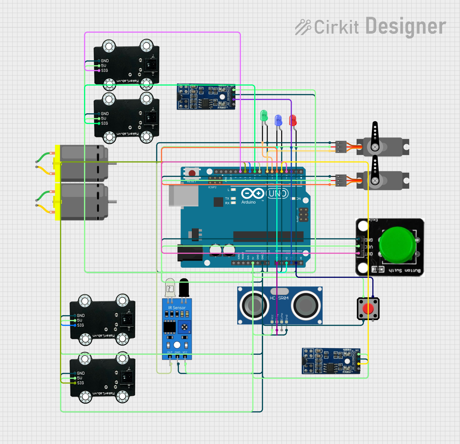
Circuit Documentation
Summary
This document provides a detailed overview of a circuit that includes an Arduino UNO microcontroller, various sensors (line follower, ultrasonic, IR, and hall sensors), servos, DC motors, LEDs, and pushbuttons. The circuit is designed to interface these components with the Arduino UNO to perform various tasks, such as sensing, actuation, and user interaction.
Component List
Arduino UNO
- Description: A microcontroller board based on the ATmega328P.
- Pins: UNUSED, IOREF, Reset, 3.3V, 5V, GND, Vin, A0, A1, A2, A3, A4, A5, SCL, SDA, AREF, D13, D12, D11, D10, D9, D8, D7, D6, D5, D4, D3, D2, D1, D0
DC Motor
- Description: A simple DC motor.
- Pins: pin 1, pin 2
Servo
- Description: A servo motor for precise control of angular position.
- Pins: GND, VCC, PWM
MKE-S10 CNY70 Line Follower Sensor
- Description: A line follower sensor.
- Pins: GND, 5V, SIG
HC-SR04 Ultrasonic Sensor
- Description: An ultrasonic distance sensor.
- Pins: VCC, TRIG, ECHO, GND
LED: Two Pin (red)
- Description: A red LED.
- Pins: cathode, anode
LED: Two Pin (green)
- Description: A green LED.
- Pins: cathode, anode
LED: Two Pin (blue)
- Description: A blue LED.
- Pins: cathode, anode
Hall sensor (magnetic)
- Description: A magnetic hall sensor.
- Pins: VCC (5V), GND, D0 (Digital), A0 (Analog)
IR Sensor
- Description: An infrared sensor.
- Pins: out, gnd, vcc
Green Button
- Description: A green pushbutton.
- Pins: OUT, VCC, GND
Red Pushbutton
- Description: A red pushbutton.
- Pins: Pin 2, Pin 1, Pin 3, Pin 4
Wiring Details
Arduino UNO
5V is connected to:
- VCC of HC-SR04 Ultrasonic Sensor
- 5V of all MKE-S10 CNY70 Line Follower Sensors
- VCC of both Servos
- VCC of IR Sensor
- VCC of both Hall Sensors
- VCC of Green Button
- Pin 1 of Red Pushbutton
GND is connected to:
- GND of HC-SR04 Ultrasonic Sensor
- GND of all MKE-S10 CNY70 Line Follower Sensors
- GND of both Servos
- GND of IR Sensor
- GND of both Hall Sensors
- GND of Green Button
- Pin 2 of Red Pushbutton
- Anode of all LEDs (Red, Green, Blue)
A0 is connected to TRIG of HC-SR04 Ultrasonic Sensor
A2 is connected to Cathode of Blue LED
A3 is connected to Cathode of Red LED
A4 is connected to Pin 4 of Red Pushbutton
D12 is connected to SIG of one MKE-S10 CNY70 Line Follower Sensor
D11 is connected to SIG of another MKE-S10 CNY70 Line Follower Sensor
D10 is connected to SIG of another MKE-S10 CNY70 Line Follower Sensor
D9 is connected to SIG of another MKE-S10 CNY70 Line Follower Sensor
D8 is connected to OUT of IR Sensor
D7 is connected to PWM of one Servo
D6 is connected to Cathode of Green LED
D5 is connected to PWM of another Servo
D4 is connected to D0 (Digital) of one Hall Sensor
D3 is connected to OUT of Green Button
D2 is connected to D0 (Digital) of another Hall Sensor
DC Motor
- pin 1 and pin 2 are not connected in the provided net list.
Servo
- GND is connected to GND of Arduino UNO
- VCC is connected to 5V of Arduino UNO
- PWM is connected to:
- D7 of Arduino UNO (for one Servo)
- D5 of Arduino UNO (for another Servo)
MKE-S10 CNY70 Line Follower Sensor
- GND is connected to GND of Arduino UNO
- 5V is connected to 5V of Arduino UNO
- SIG is connected to:
- D12 of Arduino UNO (for one sensor)
- D11 of Arduino UNO (for another sensor)
- D10 of Arduino UNO (for another sensor)
- D9 of Arduino UNO (for another sensor)
HC-SR04 Ultrasonic Sensor
- VCC is connected to 5V of Arduino UNO
- GND is connected to GND of Arduino UNO
- TRIG is connected to A0 of Arduino UNO
- ECHO is not connected in the provided net list.
LED: Two Pin (red)
- cathode is connected to A3 of Arduino UNO
- anode is connected to GND of Arduino UNO
LED: Two Pin (green)
- cathode is connected to D6 of Arduino UNO
- anode is connected to GND of Arduino UNO
LED: Two Pin (blue)
- cathode is connected to A2 of Arduino UNO
- anode is connected to GND of Arduino UNO
Hall sensor (magnetic)
- VCC (5V) is connected to 5V of Arduino UNO
- GND is connected to GND of Arduino UNO
- D0 (Digital) is connected to:
- D4 of Arduino UNO (for one sensor)
- D2 of Arduino UNO (for another sensor)
- A0 (Analog) is not connected in the provided net list.
IR Sensor
- out is connected to D8 of Arduino UNO
- gnd is connected to GND of Arduino UNO
- vcc is connected to 5V of Arduino UNO
Green Button
- OUT is connected to D3 of Arduino UNO
- VCC is connected to 5V of Arduino UNO
- GND is connected to GND of Arduino UNO
Red Pushbutton
- Pin 1 is connected to 5V of Arduino UNO
- Pin 2 is connected to GND of Arduino UNO
- Pin 4 is connected to A4 of Arduino UNO
- Pin 3 is not connected in the provided net list.
Documented Code
Arduino UNO Code (sketch.ino)
void setup() {
  // put your setup code here, to run once:

}

void loop() {
  // put your main code here, to run repeatedly:

}
Additional Documentation (documentation.txt)
This document provides a comprehensive overview of the circuit, including a summary, component list, wiring details, and documented code.