
Circuit Documentation
Summary of the Circuit
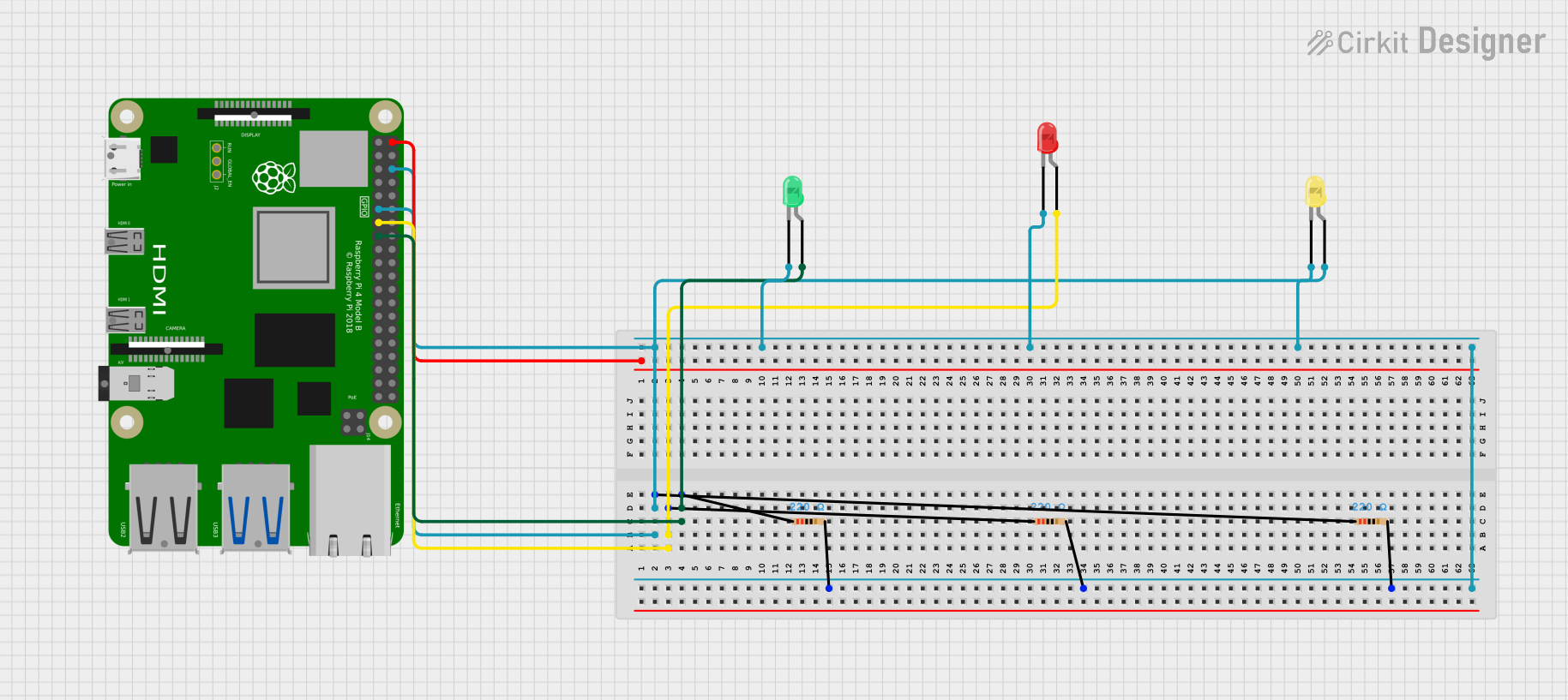
This circuit consists of a Raspberry Pi 4B microcontroller unit (MCU) that controls three LEDs (green, red, and yellow). Each LED is connected to the Raspberry Pi via a 220-ohm resistor to limit the current flowing through the LEDs. The cathodes of all LEDs are connected to the ground (GND) of the Raspberry Pi, forming a common ground. The anodes of each LED are connected to different GPIO pins on the Raspberry Pi through their respective resistors. This setup allows the Raspberry Pi to control the state (on/off) of each LED independently by setting the GPIO pins to a high or low state.
Component List
LEDs
- LED: Two Pin (green): A green LED with two pins, anode and cathode.
- LED: Two Pin (red): A red LED with two pins, anode and cathode.
- LED: Two Pin (yellow): A yellow LED with two pins, anode and cathode.
Microcontroller
- Raspberry Pi 4B: A powerful microcontroller with multiple GPIO pins, capable of driving LEDs and performing various other tasks.
Resistors
- Resistor: Three resistors with a resistance of 220 ohms each, used to limit the current through the LEDs.
Wiring Details
LED: Two Pin (green)
- Cathode: Connected to the common ground net.
- Anode: Connected to GPIO22 of the Raspberry Pi through a 220-ohm resistor.
LED: Two Pin (red)
- Cathode: Connected to the common ground net.
- Anode: Connected to GPIO27 of the Raspberry Pi through a 220-ohm resistor.
LED: Two Pin (yellow)
- Cathode: Connected to the common ground net.
- Anode: Connected to GPIO17 of the Raspberry Pi through a 220-ohm resistor.
Raspberry Pi 4B
- GPIO22: Connected to the anode of the green LED through a 220-ohm resistor.
- GPIO27: Connected to the anode of the red LED through a 220-ohm resistor.
- GPIO17: Connected to the anode of the yellow LED through a 220-ohm resistor.
- GND: Connected to the cathodes of all three LEDs.
- 5V: No connection specified.
Resistors (220 Ohms)
- Resistor for green LED: One end connected to GPIO22 of the Raspberry Pi, the other end to the anode of the green LED.
- Resistor for red LED: One end connected to GPIO27 of the Raspberry Pi, the other end to the anode of the red LED.
- Resistor for yellow LED: One end connected to GPIO17 of the Raspberry Pi, the other end to the anode of the yellow LED.
Documented Code
No code has been provided for the microcontroller. The expected behavior would be to toggle the GPIO pins connected to the LEDs to turn them on or off. Since no code is available, we cannot provide further documentation on the software aspect of this circuit.