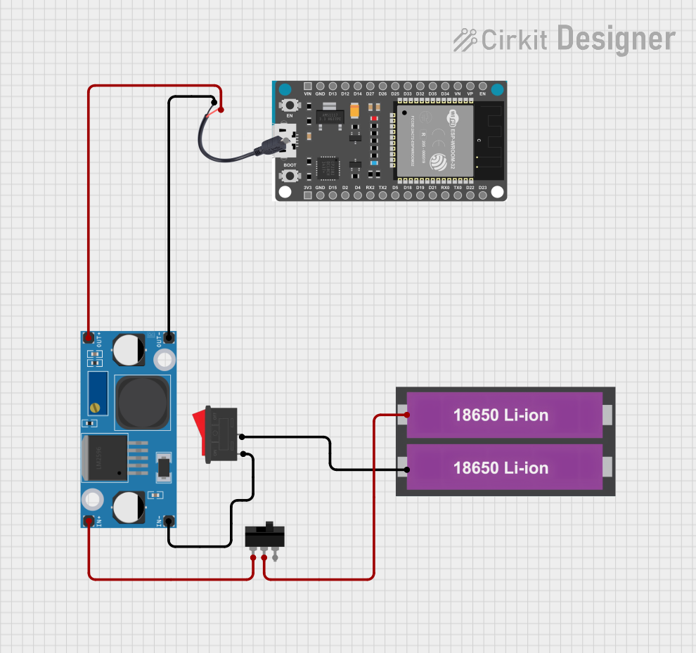
Battery-Powered ESP32 Devkit V1 with Buck Converter and Switch Control

Circuit Documentation
Summary
This document provides a detailed overview of a circuit that includes a power supply, switches, a buck converter, and an ESP32 microcontroller. The circuit is designed to manage power distribution and control using various switches and a DC-DC buck converter to step down voltage. The ESP32 microcontroller is included for potential control and monitoring tasks.
Component List
18650 Li-ion Battery x 2
- Pins: +, -
- Description: Provides the primary power source for the circuit.
- Purpose: Supplies power to the entire circuit.
Rocker Switch
- Pins: 1, 2
- Description: A simple on/off switch.
- Purpose: Controls the connection between the battery and the buck converter.
Toggle Switch
- Pins: L1, COM, L2
- Description: A switch that can toggle between two positions.
- Purpose: Selects the input to the buck converter.
LM2956 Buck Converter DC-DC
- Pins: OUT+, OUT-, IN+, IN-
- Description: A DC-DC converter that steps down voltage.
- Purpose: Converts the battery voltage to a lower voltage suitable for the ESP32 and other components.
ESP32 Devkit V1
- Pins: 3V3, GND, D15, D2, D4, RX2, TX2, D5, D18, D19, D21, RX0, TX0, D22, D23, EN, VP, VN, D34, D35, D32, D33, D25, D26, D27, D14, D12, D13, VIN
- Description: A microcontroller with Wi-Fi and Bluetooth capabilities.
- Purpose: Provides control and monitoring capabilities for the circuit.
Micro USB to Cable (2 Pin)
- Pins: Micro USB, +, -
- Description: A cable to connect the circuit to a USB power source.
- Purpose: Provides an alternative power input to the circuit.
Wiring Details
18650 Li-ion Battery x 2
- + Pin:
- Connected to COM pin of the Toggle Switch.
- - Pin:
- Connected to 2 pin of the Rocker Switch.
Rocker Switch
- 1 Pin:
- Connected to IN- pin of the LM2956 Buck Converter DC-DC.
- 2 Pin:
- Connected to - pin of the 18650 Li-ion Battery x 2.
Toggle Switch
- COM Pin:
- Connected to + pin of the 18650 Li-ion Battery x 2.
- L1 Pin:
- Connected to IN+ pin of the LM2956 Buck Converter DC-DC.
LM2956 Buck Converter DC-DC
- IN+ Pin:
- Connected to L1 pin of the Toggle Switch.
- IN- Pin:
- Connected to 1 pin of the Rocker Switch.
- OUT+ Pin:
- Connected to + pin of the Micro USB to Cable (2 Pin).
- OUT- Pin:
- Connected to - pin of the Micro USB to Cable (2 Pin).
Micro USB to Cable (2 Pin)
- + Pin:
- Connected to OUT+ pin of the LM2956 Buck Converter DC-DC.
- - Pin:
- Connected to OUT- pin of the LM2956 Buck Converter DC-DC.
ESP32 Devkit V1
- VIN Pin:
- Not connected in this circuit.
- GND Pin:
- Not connected in this circuit.
- Other Pins:
- Not connected in this circuit.
Code
There is no code provided for the microcontrollers in this circuit.
This documentation provides a comprehensive overview of the circuit, including a summary, detailed component list, wiring details, and code documentation. This should serve as a useful reference for understanding and replicating the circuit.