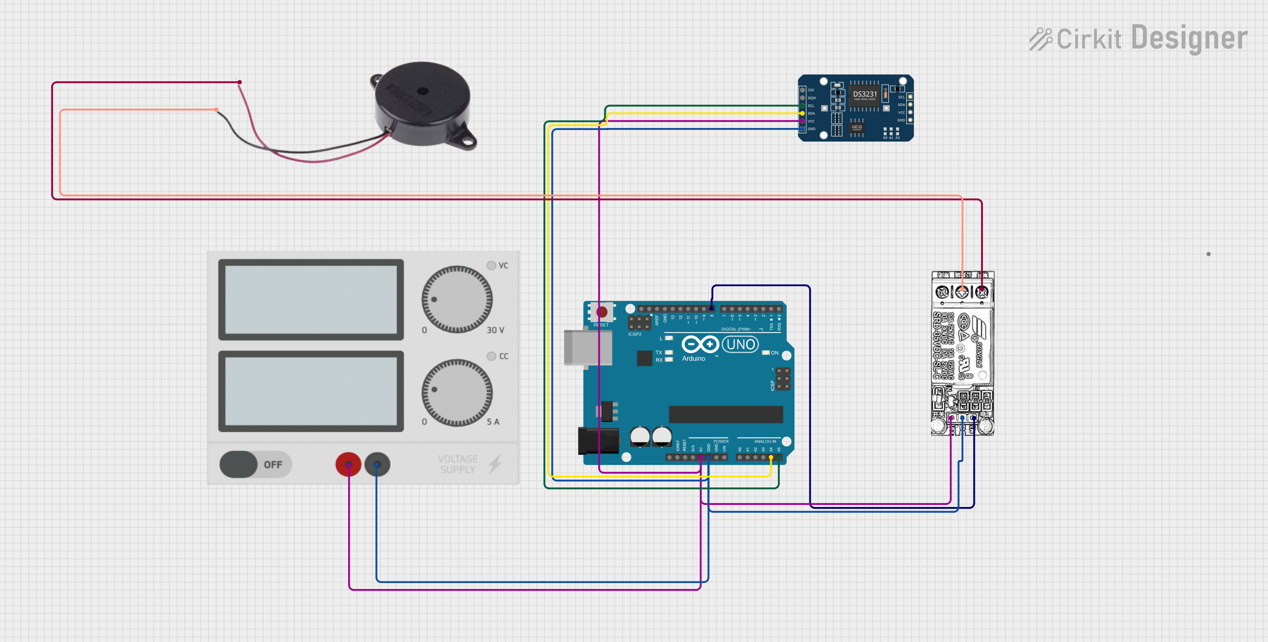
Arduino UNO Controlled School Bell System with DS3231 RTC and Relay Module

Automatic School Bell System Circuit Documentation
Summary
The Automatic School Bell System is designed to automate the ringing of a school bell at predetermined times throughout the school day. The system consists of an Arduino UNO microcontroller, a buzzer, a DS3231 Real-Time Clock (RTC) module, a relay module, and a power supply. The Arduino UNO is programmed to trigger the relay, which in turn activates the buzzer at the start of each school period. The DS3231 RTC module is used to keep track of the current time, ensuring the bell rings at the correct intervals.
Component List
Arduino UNO
- Description: A microcontroller board based on the ATmega328P.
- Purpose: Acts as the central processing unit of the circuit, controlling the timing and activation of the bell.
Buzzer
- Description: An electromechanical component that produces an audible tone when powered.
- Purpose: Serves as the bell, emitting sound when activated by the relay.
DS3231 RTC
- Description: A highly accurate I2C real-time clock with an integrated temperature-compensated crystal oscillator (TCXO) and crystal.
- Purpose: Keeps track of the current time to facilitate the timely ringing of the bell.
Relay Module
- Description: An electrically operated switch that allows a low-power signal to control a higher power circuit.
- Purpose: Acts as an intermediary between the Arduino and the buzzer, allowing the microcontroller to safely control the high-power circuit of the buzzer.
Power Supply
- Description: A module that provides electrical power to the circuit.
- Purpose: Supplies the necessary voltage and current to power the components of the circuit.
Wiring Details
Arduino UNO
- 5V: Connected to the power supply's positive output.
- GND: Connected to the power supply's negative output.
- A4 (SDA): Connected to the SDA pin of the DS3231 RTC.
- A5 (SCL): Connected to the SCL pin of the DS3231 RTC.
- D8: Connected to the INPUT pin of the relay module.
Buzzer
- POSITIVE: Connected to the NC (Normally Closed) pin of the relay module.
- NEGATIVE: Connected to the COM (Common) pin of the relay module.
DS3231 RTC
- VCC: Connected to the power supply's positive output.
- GND: Connected to the power supply's negative output.
- SDA: Connected to the SDA pin (A4) of the Arduino UNO.
- SCL: Connected to the SCL pin (A5) of the Arduino UNO.
Relay Module
- VCC: Connected to the power supply's positive output.
- GND: Connected to the power supply's negative output.
- INPUT: Connected to the D8 pin of the Arduino UNO.
- NC (Normally Closed): Connected to the POSITIVE pin of the buzzer.
- COM (Common): Connected to the NEGATIVE pin of the buzzer.
Power Supply
- + (Positive): Connected to the 5V pins of the Arduino UNO, DS3231 RTC, and VCC of the relay module.
- - (Negative): Connected to the GND pins of the Arduino UNO, DS3231 RTC, and GND of the relay module.
Documented Code
/*
 * Automatic School Bell System
 * This code controls a school bell that rings at the start of each period.
 * There are 6 periods in total: 3 in the morning (9:00-12:00) and 3 in the
 * afternoon (12:45-15:45). The bell rings at the start of each period.
 */

const int bellPin = 8; // Pin connected to the bell

void setup() {
  pinMode(bellPin, OUTPUT); // Set bell pin as output
  digitalWrite(bellPin, LOW); // Ensure bell is off initially
}

void loop() {
  unsigned long currentMillis = millis();
  unsigned long periodStartTimes[] = {
    9 * 60 * 60 * 1000, // 9:00 AM
    10 * 60 * 60 * 1000, // 10:00 AM
    11 * 60 * 60 * 1000, // 11:00 AM
    12 * 60 * 60 * 1000 + 45 * 60 * 1000, // 12:45 PM
    13 * 60 * 60 * 1000 + 45 * 60 * 1000, // 1:45 PM
    14 * 60 * 60 * 1000 + 45 * 60 * 1000 // 2:45 PM
  };

  for (int i = 0; i < 6; i++) {
    if (currentMillis >= periodStartTimes[i] &&
        currentMillis < periodStartTimes[i] + 1000) {
      ringBell();
    }
  }
}

void ringBell() {
  digitalWrite(bellPin, HIGH); // Turn bell on
  delay(5000); // Ring bell for 5 seconds
  digitalWrite(bellPin, LOW); // Turn bell off
}
Note: The code provided assumes that the Arduino's internal clock is set correctly and that the millis() function returns the number of milliseconds since the Arduino started running the current program. The ringBell() function activates the bell for 5 seconds at the start of each period.