Arduino-Controlled Obstacle-Avoiding Robot with Ultrasonic Sensors and L298N Motor Driver
Circuit Documentation
Summary
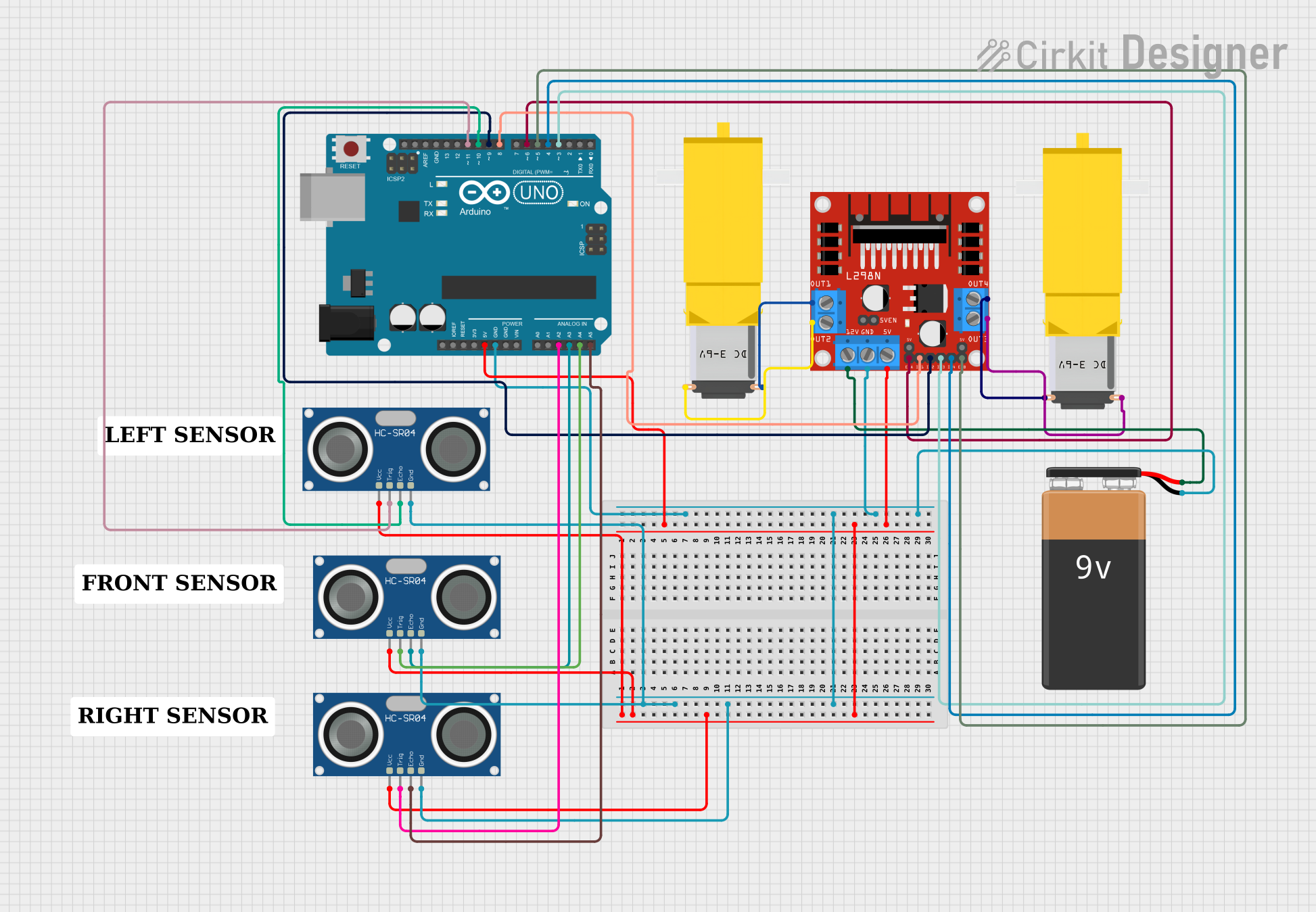
This circuit is designed to control a pair of DC gearmotors using an L298N motor driver module, with an Arduino UNO as the central microcontroller. The circuit includes three HC-SR04 ultrasonic sensors for distance measurement, which are interfaced with the Arduino to facilitate obstacle detection and navigation. The motor driver module is powered by a 9V battery and is responsible for driving the motors based on the signals from the Arduino. The Arduino executes a control algorithm, which is programmed to make decisions based on the input from the ultrasonic sensors to navigate through an environment by avoiding obstacles.
Component List
9V Battery
- Description: Provides the power supply for the motor driver and indirectly for the motors.
- Pins:
-(Negative),+(Positive)
Arduino UNO
- Description: Acts as the central processing unit of the circuit, interfacing with sensors and controlling the motor driver.
- Pins:
UNUSED,IOREF,Reset,3.3V,5V,GND,Vin,A0toA5,SCL,SDA,AREF,D13toD0
L298N DC Motor Driver
- Description: Controls the direction and speed of the DC gearmotors.
- Pins:
OUT1,OUT2,12V,GND,5V,OUT3,OUT4,5V-ENA-JMP-I,5V-ENA-JMP-O,+5V-J1,+5V-J2,ENA,IN1,IN2,IN3,IN4,ENB
Gearmotor DC / Motorreductor (2 units)
- Description: Provides the mechanical action for the circuit's operation.
- Pins:
Pin1,Pin2
HC-SR04 Ultrasonic Sensor (3 units)
- Description: Measures distances by emitting ultrasonic waves and detecting their reflections.
- Pins:
VCC,TRIG,ECHO,GND
Comments (3 units)
- Description: Placeholder for additional notes or labels within the circuit, not an actual electronic component.
Wiring Details
9V Battery
-connected toGNDon the L298N DC motor driver.+connected to12Von the L298N DC motor driver.
Arduino UNO
5Vconnected toVCCon all HC-SR04 Ultrasonic Sensors and5Von the L298N DC motor driver.GNDconnected toGNDon all HC-SR04 Ultrasonic Sensors,GNDon the L298N DC motor driver, and-on the 9V Battery.A2connected toTRIGon one HC-SR04 Ultrasonic Sensor.A3connected toECHOon another HC-SR04 Ultrasonic Sensor.A4connected toTRIGon another HC-SR04 Ultrasonic Sensor.A5connected toECHOon another HC-SR04 Ultrasonic Sensor.D11connected toTRIGon one HC-SR04 Ultrasonic Sensor.D10connected toECHOon one HC-SR04 Ultrasonic Sensor.D9connected toIN2on the L298N DC motor driver.D8connected toIN1on the L298N DC motor driver.D6connected toENAon the L298N DC motor driver.D5connected toENBon the L298N DC motor driver.D4connected toIN4on the L298N DC motor driver.D3connected toIN3on the L298N DC motor driver.
L298N DC Motor Driver
OUT1connected toPin2on one Gearmotor DC.OUT2connected toPin1on the same Gearmotor DC.OUT3connected toPin2on the other Gearmotor DC.OUT4connected toPin1on the other Gearmotor DC.
HC-SR04 Ultrasonic Sensors
VCCconnected to5Von the Arduino UNO.GNDconnected toGNDon the Arduino UNO.TRIGandECHOpins connected to various digital pins on the Arduino UNO as specified in the wiring details above.
Documented Code
const int trigPin1 = 11;
const int echoPin1 = 10;
const int trigPin2 = A3;
const int echoPin2 = A4;
const int trigPin3 = A2;
const int echoPin3 = A5;
const int in1 = 9;
const int in2 = 8;
const int in3 = 4;
const int in4 = 3;
const int enA = 5;
const int enB = 6;

#define PWM 200
#define DIS 25

void setup() {
    pinMode(trigPin1, OUTPUT);
    pinMode(echoPin1, INPUT);
    pinMode(trigPin2, OUTPUT);
    pinMode(echoPin2, INPUT);
    pinMode(trigPin3, OUTPUT);
    pinMode(echoPin3, INPUT);
    pinMode(in1, OUTPUT);
    pinMode(in2, OUTPUT);
    pinMode(in3, OUTPUT);
    pinMode(in4, OUTPUT);
    pinMode(enA, OUTPUT);
    pinMode(enB, OUTPUT);
}

void loop() {
    if (FrontSensor() < DIS && RightSensor() < DIS && LeftSensor() < DIS) {
        turn_right();
        delay(3000);
    } else if (FrontSensor() < DIS && RightSensor() < DIS && LeftSensor() > DIS) {
        turn_left();
    } else if (FrontSensor() < DIS && RightSensor() > DIS && LeftSensor() < DIS) {
        turn_right();
    } else if (FrontSensor() < DIS && RightSensor() > DIS && LeftSensor() > DIS) {
        turn_right();
    } else if (FrontSensor() > DIS && RightSensor() > DIS && LeftSensor() < DIS) {
        turn_right();
        delay(180);
        forward();
    } else if (FrontSensor() > DIS && RightSensor() < DIS && LeftSensor() > DIS) {
        turn_left();
        delay(180);
        forward();
    } else {
        forward();
    }
}

void forward() {
    digitalWrite(in1, HIGH);
    digitalWrite(in2, LOW);
    digitalWrite(in3, HIGH);
    digitalWrite(in4, LOW);
    analogWrite(enA, PWM);
    analogWrite(enB, PWM);
}

void turn_left() {
    digitalWrite(in1, HIGH);
    digitalWrite(in2, LOW);
    digitalWrite(in3, LOW);
    digitalWrite(in4, HIGH);
    analogWrite(enA, PWM);
    analogWrite(enB, PWM);
}

void turn_right() {
    digitalWrite(in1, LOW);
    digitalWrite(in2, HIGH);
    digitalWrite(in3, HIGH);
    digitalWrite(in4, LOW);
    analogWrite(enA, PWM);
    analogWrite(enB, PWM);
}

void reverse() {
    digitalWrite(in1, LOW);
    digitalWrite(in2, HIGH);
    digitalWrite(in3, LOW);
    digitalWrite(in4, HIGH);
    analogWrite(enA, PWM);
    analogWrite(enB, PWM);
}

void stop() {
    digitalWrite(in1, LOW);
    digitalWrite(in2, LOW);
    digitalWrite(in3, LOW);
    digitalWrite(in4, LOW);
    analogWrite(enA, LOW);
    analogWrite(enB, LOW);
}

long FrontSensor() {
    long dur;
    digitalWrite(trigPin1, LOW);
    delayMicroseconds(5);
    digitalWrite(trigPin1, HIGH);
    delayMicroseconds(10);
    digitalWrite(trigPin1, LOW);
    dur = pulseIn(echoPin1, HIGH);
    return (dur / 30); // convert the distance to centimeters
}

long RightSensor() {
    long dur;
    digitalWrite(trigPin2, LOW);
    delayMicroseconds(5);
    digitalWrite(trigPin2, HIGH);
    delayMicroseconds(10);
    digitalWrite(trigPin2, LOW);
    dur = pulseIn(echoPin2, HIGH);
    return (dur / 62); // convert the distance to centimeters
}

long LeftSensor() {
    long dur;
    digitalWrite(trigPin3, LOW);
    delayMicroseconds(5);
    digitalWrite(trigPin3, HIGH);
    delayMicroseconds(10);
    digitalWrite(trigPin3, LOW);
    dur = pulseIn(echoPin3, HIGH);
    return (dur / 50); // convert the distance to centimeters
}
This code is responsible for initializing the pins connected to the ultrasonic sensors and motor driver, and contains the main control loop which determines the robot's movement based on sensor readings. The FrontSensor, RightSensor, and LeftSensor functions are used to measure distances from obstacles, and the forward, turn_left, turn_right, reverse, and stop functions control the motors' movements.