Arduino-Powered 2.9" Greyscale eInk Display with Checkerboard Pattern
Circuit Documentation
Summary
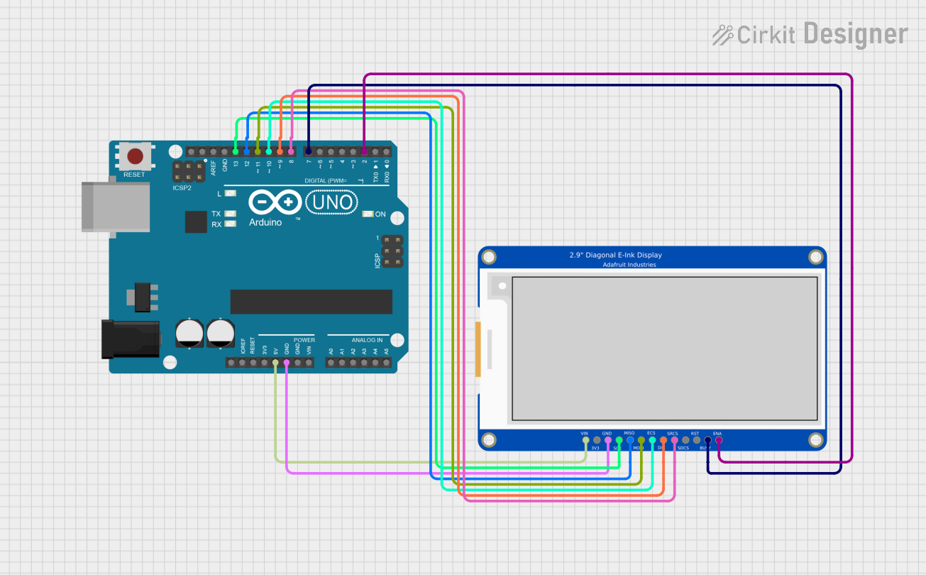
This circuit is designed to interface an Arduino UNO with a 2.9" Greyscale eInk display. The Arduino serves as the microcontroller, controlling the display through SPI communication. The code initializes the display, draws a checkerboard pattern, and allows for the inversion of the pattern after a delay. The eInk display retains the image without requiring continuous updates, making it suitable for low-power applications.
Component List
Arduino UNO
- Description: A microcontroller board based on the ATmega328P. It is used for various applications, including controlling sensors, motors, and displays.
- Purpose in Circuit: Acts as the main controller for the eInk display, handling the communication and display updates.
2.9" Greyscale eInk
- Description: A low-power display technology that retains images without power. It is suitable for applications where power consumption is critical.
- Purpose in Circuit: Displays the output from the Arduino, specifically the checkerboard pattern and its inverted version.
Wiring Details
Arduino UNO
5V: Connected to VIN of the 2.9" Greyscale eInk display.
GND: Connected to GND of the 2.9" Greyscale eInk display.
D13: Connected to SCLK of the 2.9" Greyscale eInk display.
D12: Connected to MISO of the 2.9" Greyscale eInk display.
D11: Connected to MOSI of the 2.9" Greyscale eInk display.
D10: Connected to DISPCS of the 2.9" Greyscale eInk display.
D9: Connected to DC of the 2.9" Greyscale eInk display.
D8: Connected to SRAMCS of the 2.9" Greyscale eInk display (used as RESET).
D7: Connected to BUSY of the 2.9" Greyscale eInk display.
D2: Connected to ENABLE of the 2.9" Greyscale eInk display.
Documented Code
/*
 * Arduino Sketch for interfacing with a 2.9" Greyscale eInk display.
 * This code initializes the display, draws a checkerboard pattern, and
 * then inverts the pattern after a delay. The display holds the image
 * without continuous updates. The pin connections are configured to
 * match the specified wiring between the Arduino UNO and the eInk display.
 */

#include <SPI.h>

// Pin mapping (Arduino Uno)
const int PIN_CS   = 10; // DISPCS
const int PIN_DC   = 9;  // Data/Command: LOW=cmd, HIGH=data
const int PIN_RST  = 8;  // SRAMCS (used as RESET)
const int PIN_BUSY = 7;  // BUSY (HIGH during refresh)
const int PIN_EN   = 2;  // ENABLE (HIGH to accept writes)

// Display geometry (matches simulator)
const uint16_t EPD_WIDTH  = 296;
const uint16_t EPD_HEIGHT = 128;

void epdWriteByte(uint8_t b, bool isData) {
  digitalWrite(PIN_DC, isData ? HIGH : LOW);
  digitalWrite(PIN_CS, LOW);
  SPI.transfer(b);
  digitalWrite(PIN_CS, HIGH);
}

void epdCommand(uint8_t cmd) {
  epdWriteByte(cmd, false);
}

void epdData(const uint8_t* buf, size_t len) {
  digitalWrite(PIN_DC, HIGH);
  digitalWrite(PIN_CS, LOW);
  for (size_t i = 0; i < len; i++) {
    SPI.transfer(buf[i]);
  }
  digitalWrite(PIN_CS, HIGH);
}

void epdWaitWhileBusy() {
  // BUSY goes HIGH only during refresh and returns LOW when done.
  while (digitalRead(PIN_BUSY) == HIGH) {
    delay(1);
  }
}

void epdReset() {
  digitalWrite(PIN_RST, LOW);
  delay(10);
  digitalWrite(PIN_RST, HIGH);
  delay(10);
}

void drawCheckerboard() {
  // Send WRITE RAM (0x24), then stream 1bpp pixels (MSB first).
  epdCommand(0x24);

  const uint16_t bytesPerRow = EPD_WIDTH / 8; // 296/8 = 37
  uint8_t rowBuf[bytesPerRow];

  for (uint16_t y = 0; y < EPD_HEIGHT; y++) {
    for (uint16_t bx = 0; bx < bytesPerRow; bx++) {
      uint8_t b = 0;
      for (int bit = 7; bit >= 0; bit--) {
        uint16_t x = bx * 8 + (7 - bit); // MSB is leftmost pixel
        // 8x8 checkerboard: white=1, black=0
        bool white = (((x / 8) + (y / 8)) % 2) == 0;
        b |= (white ? 1 : 0) << bit;
      }
      rowBuf[bx] = b;
    }
    epdData(rowBuf, bytesPerRow);
  }

  // Trigger display refresh (0x20)
  epdCommand(0x20);
  epdWaitWhileBusy();
}

void setup() {
  // Pins
  pinMode(PIN_CS, OUTPUT);
  pinMode(PIN_DC, OUTPUT);
  pinMode(PIN_RST, OUTPUT);
  pinMode(PIN_BUSY, INPUT);
  pinMode(PIN_EN, OUTPUT);

  // Ensure proper idle states
  digitalWrite(PIN_CS, HIGH);
  digitalWrite(PIN_DC, HIGH);
  digitalWrite(PIN_RST, HIGH);
  digitalWrite(PIN_EN, HIGH); // ENABLE the panel for writes

  // SPI init (Mode 0, MSB first). Speed not critical in simulator.
  SPI.begin();
  SPI.beginTransaction(SPISettings(4000000, MSBFIRST, SPI_MODE0));

  // Panel reset + software reset
  epdReset();
  epdCommand(0x12);   // SWRESET
  delay(10);

  // Draw first image
  drawCheckerboard();

  // Optional: after a pause, invert the checkerboard to verify a second update
  delay(2000);

  // Write inverted checkerboard
  epdCommand(0x24);
  const uint16_t bytesPerRow = EPD_WIDTH / 8;
  for (uint16_t y = 0; y < EPD_HEIGHT; y++) {
    for (uint16_t bx = 0; bx < bytesPerRow; bx++) {
      uint8_t b = 0;
      for (int bit = 7; bit >= 0; bit--) {
        uint16_t x = bx * 8 + (7 - bit);
        bool white = (((x / 8) + (y / 8)) % 2) != 0; // inverted
        b |= (white ? 1 : 0) << bit;
      }
      epdWriteByte(b, true);
    }
  }
  epdCommand(0x20);
  epdWaitWhileBusy();

  // Done. Leave SPI configured.
}

void loop() {
  // No continuous updates required for ePaper; it holds image.
}
This documentation provides a comprehensive overview of the circuit, detailing the components used, their connections, and the code that drives the functionality of the eInk display.