ESP32-CAM Based Smart Security System with Face Recognition and Remote Notifications
Circuit Documentation
Summary
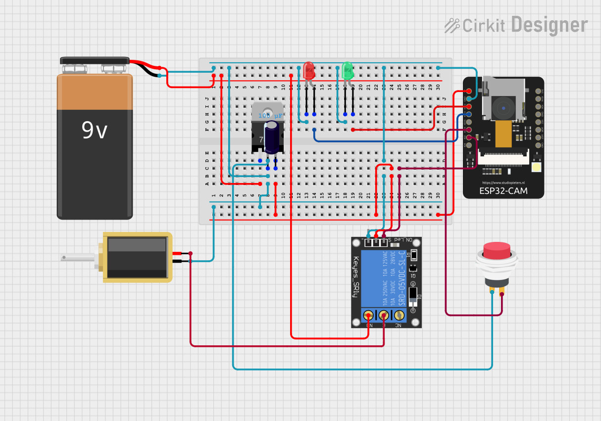
The circuit design incorporates an ESP32-CAM module, which is the central processing unit capable of image capture and face recognition. The circuit also includes a solenoid, a voltage regulator, two LEDs (green and red), a 1-channel relay, a 9V battery, an electrolytic capacitor, and a 2-pin push switch. The ESP32-CAM is responsible for capturing images and running the embedded code for face recognition, which interacts with other components to trigger actions based on the recognition results.
Component List
ESP32-CAM
- Description: A small-sized ESP32-based board with an integrated camera and microSD card slot.
- Purpose: Acts as the main controller and image processing unit, capable of Wi-Fi communication and camera operations.
Solenoid
- Description: An electromechanical device used as an actuator.
- Purpose: To perform physical actions, such as locking or unlocking a mechanism, when activated by the ESP32-CAM.
Voltage Regulator (V_REG_LD1117VXX)
- Description: A low-dropout voltage regulator with a fixed or adjustable output.
- Purpose: To regulate the input voltage to a stable output voltage for the circuit.
LED: Two Pin (green)
- Description: A basic green LED.
- Purpose: To indicate a successful operation or status, such as a recognized face.
LED: Two Pin (red)
- Description: A basic red LED.
- Purpose: To indicate an unsuccessful operation or status, such as an unrecognized face.
1-Channel Relay (5V 10A)
- Description: An electromechanical switch that can be controlled by a low-power signal.
- Purpose: To electrically isolate and control high-power devices like the solenoid.
9V Battery
- Description: A standard 9V battery.
- Purpose: To provide power to the circuit.
Electrolytic Capacitor
- Description: A polarized capacitor with a capacitance value of 0.0001 Farads.
- Purpose: To smooth out voltage fluctuations and provide power supply decoupling.
2Pin Push Switch
- Description: A simple push-button switch.
- Purpose: To manually trigger an action or event in the circuit.
Wiring Details
ESP32-CAM
5Vto Voltage RegulatorINGNDto common groundIO12to Green LEDanodeIO13to Red LEDanodeIO2to RelaysignalIO14to Push SwitchOutput +
Solenoid
pin1to RelayNOpin2to RelayC
Voltage Regulator (V_REG_LD1117VXX)
GNDto common groundOUTto ESP32-CAM5VINto 9V Battery+
LED: Two Pin (green)
cathodeto common groundanodeto ESP32-CAMIO12
LED: Two Pin (red)
cathodeto common groundanodeto ESP32-CAMIO13
1-Channel Relay (5V 10A)
NCnot connectedsignalto ESP32-CAMIO2Cto Solenoidpin2powerto Voltage RegulatorOUTNOto Solenoidpin1groundto common ground
9V Battery
+to Voltage RegulatorIN-to common ground
Electrolytic Capacitor
+to Voltage RegulatorIN-to common ground
2Pin Push Switch
Input +to Voltage RegulatorOUTOutput +to ESP32-CAMIO14
Documented Code
The embedded code for the ESP32-CAM is written in C++ and is designed to perform face recognition using the camera module. The code includes the Blynk library for IoT applications, allowing remote interactions and notifications. The camera initialization and configuration are set up in the setup() function, while the loop() function continuously checks for button presses to trigger face recognition and take photos. The code also includes a web server setup for streaming video and capturing images, which can be accessed via HTTP requests.
The face recognition algorithm uses a multi-task cascaded convolutional neural network (MTCNN) for detecting faces and a recognition model to match detected faces with enrolled faces. When a known face is detected, the green LED is turned on, and the solenoid can be activated to unlock a door. If an unknown face is detected, the red LED is turned on.
The code also includes HTML and CSS files for the web interface, which provides a live video stream from the camera and buttons for controlling the camera settings and face recognition features.
The camera pins are defined in a separate header file, camera_pins.h, which maps the ESP32-CAM GPIOs to the camera module pins based on the selected camera model. The web server functionality is implemented in app_httpd.h, which sets up the endpoints for the web interface and handles HTTP requests for streaming video, capturing images, and controlling camera settings.