ESP32-Based GPS Tracker with Bluetooth Connectivity and Camera Interface
Circuit Documentation
Summary
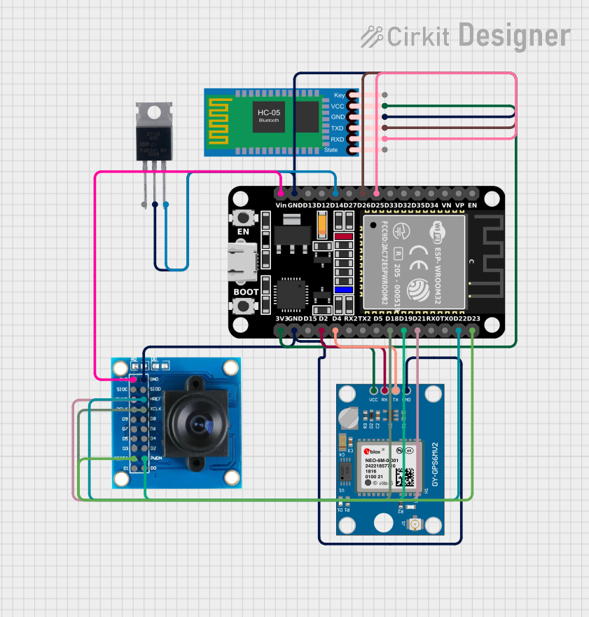
The circuit in question is designed to interface an ESP32 microcontroller with several peripheral modules, including a Neo 6M GPS Module, an OV7725 camera module, an HC-05 Bluetooth Module, and a BT139 600 triac. The ESP32 is responsible for processing data from the GPS module, controlling the camera module, and communicating with external devices via Bluetooth. Additionally, the ESP32 can control power flow through the triac. The circuit is powered through the ESP32's 3V3 pin, which supplies power to the other modules.
Component List
ESP32 (30 pin)
- Description: A microcontroller with Wi-Fi and Bluetooth capabilities.
- Pins: EN, VP, VN, D34, D35, D32, D33, D25, D26, D27, D14, D12, D13, GND, Vin, D23, D22, TX0, RX0, D21, D19, D18, D5, TX2, RX2, D4, D2, D15, 3V3
Neo 6M GPS Module
- Description: A GPS receiver module for satellite navigation.
- Pins: GND, TX, RX, VCC
BT139 600
- Description: A triac used for controlling AC power.
- Pins: MT1, MT2, GATE
OV7725
- Description: A camera module capable of capturing images and video.
- Pins: 3V3, GND, SIOC, SIOD, VSYNC, HREF, PCLK, XCLK, D9, D8, D7, D6, D5, D4, D3, D2, RESET, D1, D0, PWDN
HC-05 Bluetooth Module
- Description: A Bluetooth module for wireless communication.
- Pins: Key, VCC, GND, TXD, RXD, State
Wiring Details
ESP32 (30 pin)
- D25 connected to HC-05 Bluetooth Module RXD
- D26 connected to HC-05 Bluetooth Module TXD
- D14 connected to BT139 600 GATE
- GND connected to BT139 600 MT2, HC-05 Bluetooth Module GND, OV7725 GND, Neo 6M GPS Module GND
- Vin connected to OV7725 3V3
- D23 connected to OV7725 RESET
- D22 connected to OV7725 HREF
- D21 connected to OV7725 VSYNC
- D19 connected to OV7725 PWDN
- D18 connected to OV7725 XCLK
- D4 connected to Neo 6M GPS Module TX
- D2 connected to Neo 6M GPS Module RX
- 3V3 connected to Neo 6M GPS Module VCC, HC-05 Bluetooth Module VCC
Neo 6M GPS Module
- GND connected to ESP32 GND
- TX connected to ESP32 D4
- RX connected to ESP32 D2
- VCC connected to ESP32 3V3
BT139 600
- MT1 (no connection specified)
- MT2 connected to ESP32 GND
- GATE connected to ESP32 D14
OV7725
- 3V3 connected to ESP32 Vin
- GND connected to ESP32 GND
- SIOC (no connection specified)
- SIOD (no connection specified)
- VSYNC connected to ESP32 D21
- HREF connected to ESP32 D22
- PCLK (no connection specified)
- XCLK connected to ESP32 D18
- D9-D0 (no connection specified)
- RESET connected to ESP32 D23
- PWDN connected to ESP32 D19
HC-05 Bluetooth Module
- Key (no connection specified)
- VCC connected to ESP32 3V3
- GND connected to ESP32 GND
- TXD connected to ESP32 D26
- RXD connected to ESP32 D25
- State (no connection specified)
Documented Code
ESP32 (30 pin) - sketch.ino
#include <TinyGPS++.h>
#include <TinyGPSPlus.h>

#define GPS_BAUDRATE 9600  // The default baudrate of NEO-6M is 9600

TinyGPSPlus gps;  // the TinyGPS++ object

void setup() {
  Serial.begin(9600);
  Serial2.begin(GPS_BAUDRATE); //serial2 for GPS UART

  Serial.println(F("ESP32 - GPS module_Simulation"));
}

void loop() {
  if (Serial2.available() > 0) {
    if (gps.encode(Serial2.read())) {
      if (gps.location.isValid()) {
        Serial.print(F("Latitude: "));
        Serial.println(gps.location.lat(),6);

        Serial.print(F("Longitude: "));
        Serial.println(gps.location.lng(),6);

        Serial.print(F("Altitude: "));
        if (gps.altitude.isValid())
          Serial.println(gps.altitude.meters());
        else
          Serial.println(F("INVALID"));
      } else {
        Serial.println(F("Location: INVALID"));
      }

      Serial.print(F("Speed: "));
      if (gps.speed.isValid()) {
        Serial.print(gps.speed.kmph());
        Serial.println(F(" km/h"));
      } else {
        Serial.println(F("INVALID"));
      }

      Serial.print(F("GPS date&time: "));
      if (gps.date.isValid() && gps.time.isValid()) {
        Serial.print(gps.date.year());
        Serial.print(F("-"));
        Serial.print(gps.date.month());
        Serial.print(F("-"));
        Serial.print(gps.date.day());
        Serial.print(F(" "));
        Serial.print(gps.time.hour());
        Serial.print(F(":"));
        Serial.print(gps.time.minute());
        Serial.print(F(":"));
        Serial.println(gps.time.second());
      } else {
        Serial.println(F("INVALID"));
      }

      Serial.println();
    }
  }

  if (millis() > 5000 && gps.charsProcessed() < 10)
    Serial.println(F("No GPS data received: check wiring"));
}
This code is responsible for initializing the GPS module, reading GPS data, and outputting the location, speed, and timestamp to the serial monitor. It checks for valid GPS data and prints an error message if no data is received within the first 5 seconds.