
Arduino Mega ADK Smart Home Automation System with LCD Display and Sensor Integration
View and Edit Project In Cirkit Designer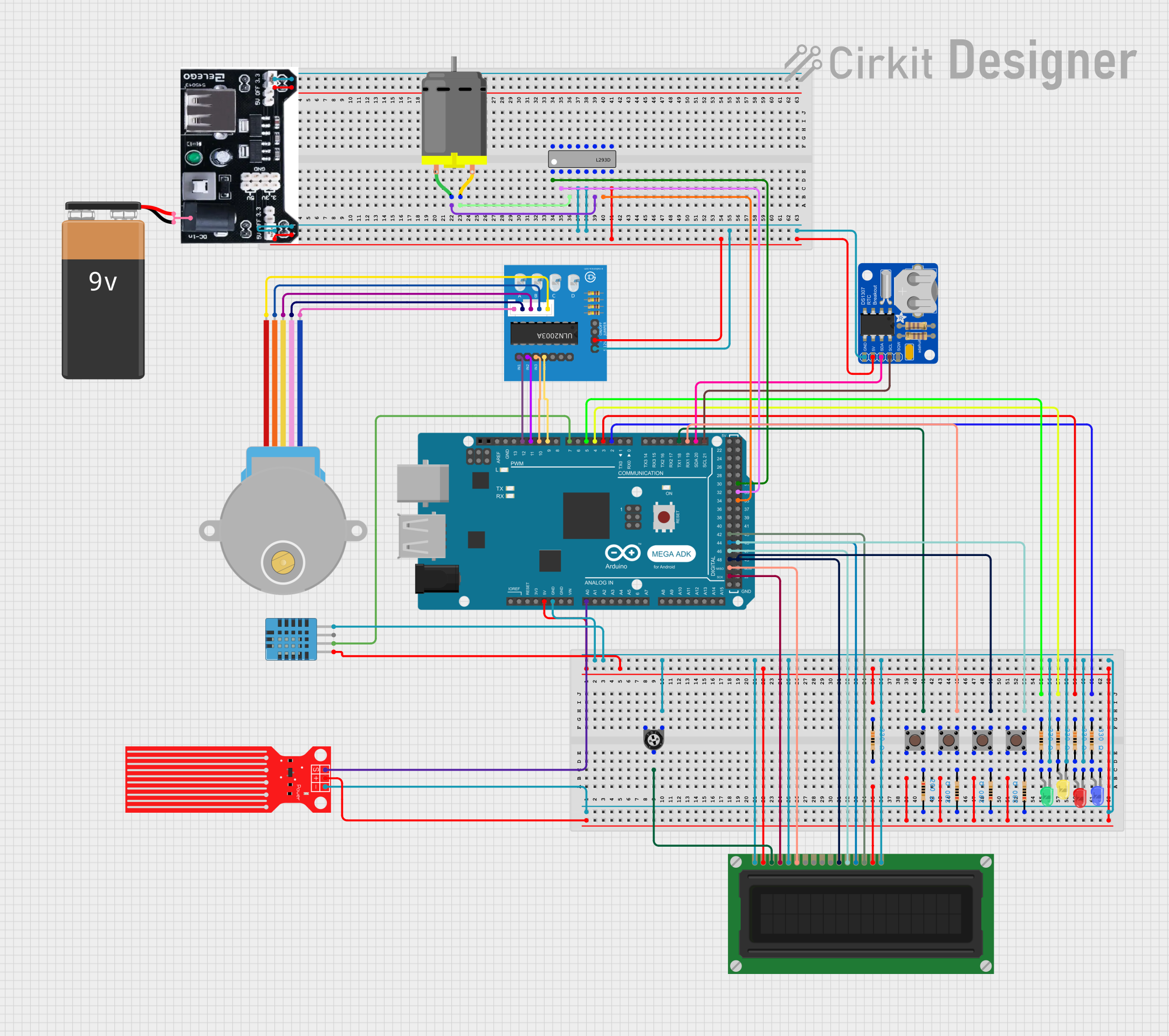
Circuit Documentation
Summary
This circuit is built around an Arduino Mega ADK (Rev3) microcontroller and includes various sensors, LEDs, a stepper motor, an LCD display, and other components. The circuit is designed to interface with multiple input and output devices, providing a comprehensive setup for a variety of applications.
Component List
Arduino Mega ADK (Rev3)
- Description: Microcontroller board based on the ATmega2560.
- Pins: A8, A9, A10, A11, A12, A13, A14, A15, A0, A1, A2, A3, A4, A5, A6, A7, D21/SCL, D20/SDA, D19/RX1, D18/TX1, D17/RX2, D16/TX2, D15/RX3, D14/TX3, ICSP2 MISO, 5V, ICSP2 SCK, ICSP2 MOSI, RESET2, GND, AREF, D13 PWM, D12 PWM, D11 PWM, D10 PWM, D9 PWM, D8 PWM, RESET, 3V3, VIN, D0/RX0, D1/TX0, D2 PWM, D3 PWM, D4 PWM, D5 PWM, D6 PWM, D7 PWM, D22, D23, D24, D25, D26, D27, D28, D29, D30, D31, D32, D33, D34, D35, D36, D37, D38, D39, D40, D41, D42, D43, D44, D45, D46, D47, D48, D49, D50/MISO, D51/MOSI, D52/SCK, D53/SS, ICSP MISO, ICSP MOSI, ICSP SCK, RESET3, IOREF.
LED: Two Pin (blue)
- Description: Blue LED.
- Pins: Cathode, Anode.
LED: Two Pin (yellow)
- Description: Yellow LED.
- Pins: Cathode, Anode.
LED: Two Pin (green)
- Description: Green LED.
- Pins: Cathode, Anode.
LED: Two Pin (red)
- Description: Red LED.
- Pins: Cathode, Anode.
Resistor (330 Ohms)
- Description: Resistor with 330 Ohms resistance.
- Pins: Pin1, Pin2.
Resistor (200 Ohms)
- Description: Resistor with 200 Ohms resistance.
- Pins: Pin1, Pin2.
Trimmer Potentiometer (10k Ohms)
- Description: Adjustable resistor.
- Pins: Leg1, Wiper, Leg2.
LCD Display (16 pin)
- Description: 16-pin LCD display.
- Pins: VSS, VDD, VO, RS, R_W, E, DB0, DB1, DB2, DB3, DB4, DB5, DB6, DB7, A, K.
Water Level Sensor
- Description: Sensor to measure water level.
- Pins: SIG, VCC, GND.
DHT11 Humidity and Temperature Sensor
- Description: Sensor to measure humidity and temperature.
- Pins: VDD, DATA, NULL, GND.
Adafruit DS1307 RTC Breakout
- Description: Real-time clock module.
- Pins: SQW, SCL, SDA, VCC, GND.
Power mb V2
- Description: Power management board.
- Pins: -, +, DC-ln.
9V Battery
- Description: 9V power source.
- Pins: -, +.
28BYJ-48 Stepper Motor
- Description: Stepper motor.
- Pins: BLUE, PINK, YELLOW, ORANGE, RED.
L293D
- Description: Motor driver IC.
- Pins: Enable 1,2, Input 1, Output 1, GND, Output 2, Input 2, VCC2, VCC1, Input 4, Output 4, Output 3, Input 3, Enable 3,4.
DC Motor
- Description: DC motor.
- Pins: Pin 1, Pin 2.
Pushbutton
- Description: Pushbutton switch.
- Pins: Pin 3 (out), Pin 4 (out), Pin 1 (in), Pin 2 (in).
ULN2003A breakout board
- Description: Darlington transistor array.
- Pins: In 1, In 2, In 3, In 4, In 5, In 6, In 7, 0V, +5V, ON/OFF jumper switch, BLUE wire, PINK wire, YELLOW wire, ORANGE wire, RED wire.
Wiring Details
Arduino Mega ADK (Rev3)
GND is connected to:
- Trimmer Potentiometer (leg1)
- LED (green) cathode
- LED (yellow) cathode
- LED (red) cathode
- DHT11 Humidity and Temperature Sensor (GND)
- LCD Display (VSS, R_W, K)
- Resistor (pin2)
- Water Level Sensor (GND)
- Adafruit DS1307 RTC Breakout (GND)
- Power mb V2 (-)
- ULN2003A breakout board (0V)
5V is connected to:
- Resistor (pin1)
- DHT11 Humidity and Temperature Sensor (VDD)
- LCD Display (VDD)
- Pushbutton (Pin 2 (in))
- Water Level Sensor (VCC)
- Adafruit DS1307 RTC Breakout (VCC)
- Power mb V2 (+)
- ULN2003A breakout board (+5V)
D18/TX1 is connected to Pushbutton (Pin 3 (out))
D19/RX1 is connected to Pushbutton (Pin 3 (out))
D49 is connected to Pushbutton (Pin 3 (out))
D45 is connected to Pushbutton (Pin 3 (out))
D5 PWM is connected to Resistor (pin1)
D4 PWM is connected to Resistor (pin1)
D3 PWM is connected to Resistor (pin1)
D2 PWM is connected to Resistor (pin1)
A0 is connected to Water Level Sensor (SIG)
D21/SCL is connected to Adafruit DS1307 RTC Breakout (SCL)
D20/SDA is connected to Adafruit DS1307 RTC Breakout (SDA)
D12 PWM is connected to ULN2003A breakout board (In 1)
D11 PWM is connected to ULN2003A breakout board (In 2)
D10 PWM is connected to ULN2003A breakout board (In 3)
D9 PWM is connected to ULN2003A breakout board (In 4)
D7 PWM is connected to DHT11 Humidity and Temperature Sensor (DATA)
D42 is connected to LCD Display (DB7)
D44 is connected to LCD Display (DB6)
D46 is connected to LCD Display (DB5)
D48 is connected to LCD Display (DB4)
D50/MISO is connected to LCD Display (E)
D52/SCK is connected to LCD Display (RS)
LED: Two Pin (blue)
- Anode is connected to Resistor (pin2)
LED: Two Pin (yellow)
- Anode is connected to Resistor (pin2)
LED: Two Pin (green)
- Anode is connected to Resistor (pin2)
LED: Two Pin (red)
- Anode is connected to Resistor (pin2)
Resistor (330 Ohms)
Pin1 is connected to:
- Arduino Mega ADK (D5 PWM)
- Arduino Mega ADK (D4 PWM)
- Arduino Mega ADK (D3 PWM)
- Arduino Mega ADK (D2 PWM)
Pin2 is connected to:
- LED (blue) anode
- LED (yellow) anode
- LED (green) anode
- LED (red) anode
Resistor (200 Ohms)
Pin1 is connected to:
- Pushbutton (Pin 4 (out))
Pin2 is