Arduino UNO Controlled Parking Sensor with Dual OLED Displays
Circuit Documentation
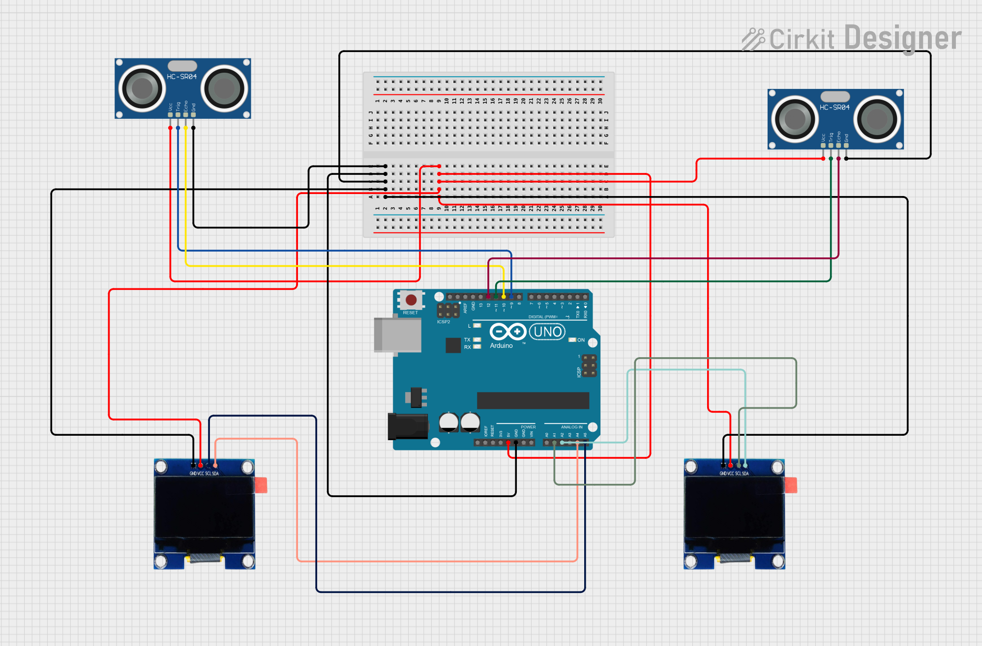
Summary
The circuit consists of an Arduino UNO microcontroller interfaced with two OLED 1.3" displays and two HC-SR04 Ultrasonic Sensors. The OLED displays are used for visual feedback, while the ultrasonic sensors are used to measure distances, likely for detecting the presence or absence of objects. The Arduino UNO controls the displays and reads data from the ultrasonic sensors. All components share a common ground (GND) and are powered by the Arduino's 5V output.
Component List
Arduino UNO
- Description: A microcontroller board based on the ATmega328P.
- Purpose: Acts as the central processing unit of the circuit, controlling the OLED displays and reading data from the ultrasonic sensors.
- Pins: IOREF, Reset, 3.3V, 5V, GND, Vin, A0-A5, SCL, SDA, AREF, D0-D13.
OLED 1.3" Display
- Description: A small display with I2C interface for visual output.
- Purpose: To provide visual feedback to the user.
- Pins: GND, VCC, SCL, SDA.
HC-SR04 Ultrasonic Sensor
- Description: An ultrasonic distance sensor.
- Purpose: To measure distances and detect the presence or absence of objects.
- Pins: VCC, TRIG, ECHO, GND.
Wiring Details
Arduino UNO
- GND: Connected to the ground pins of both OLED displays and both HC-SR04 Ultrasonic Sensors.
- 5V: Powers both OLED displays and both HC-SR04 Ultrasonic Sensors.
- A1: Connected to the SCL pin of one OLED display.
- A2: Connected to the SDA pin of one OLED display.
- A4: Connected to the SDA pin of the other OLED display.
- A5: Connected to the SCL pin of the other OLED display.
- D9: Connected to the TRIG pin of one HC-SR04 Ultrasonic Sensor.
- D10: Connected to the ECHO pin of one HC-SR04 Ultrasonic Sensor.
- D11: Connected to the TRIG pin of the other HC-SR04 Ultrasonic Sensor.
- D12: Connected to the ECHO pin of the other HC-SR04 Ultrasonic Sensor.
OLED 1.3" Display
- GND: Connected to the Arduino UNO's GND.
- VCC: Powered by the Arduino UNO's 5V.
- SCL: Connected to the Arduino UNO's A1 or A5.
- SDA: Connected to the Arduino UNO's A2 or A4.
HC-SR04 Ultrasonic Sensor
- GND: Connected to the Arduino UNO's GND.
- VCC: Powered by the Arduino UNO's 5V.
- TRIG: Connected to the Arduino UNO's D9 or D11.
- ECHO: Connected to the Arduino UNO's D10 or D12.
Documented Code
#include <Wire.h>                 // Include the Wire library for I2C communication
#include <Adafruit_GFX.h>         // Include the Adafruit GFX library
#include <Adafruit_SSD1306.h>     // Include the Adafruit SSD1306 library

#define SCREEN_WIDTH 128          // OLED screen width, in pixels
#define SCREEN_HEIGHT 64          // OLED screen height, in pixels
#define OLED_RESET    -1          // Reset pin # (or -1 if sharing Arduino reset pin)
#define SCREEN_ADDRESS 0x3C       // OLED display I2C address

Adafruit_SSD1306 display(SCREEN_WIDTH, SCREEN_HEIGHT, &Wire, OLED_RESET);

// Define pins for ultrasonic sensors
const int trigPin1 = 9;  // Trigger pin for slot 1
const int echoPin1 = 10; // Echo pin for slot 1
const int trigPin2 = 11; // Trigger pin for slot 2
const int echoPin2 = 12; // Echo pin for slot 2

void setup() {
  // Initialize OLED display
  if (!display.begin(SSD1306_SWITCHCAPVCC, SCREEN_ADDRESS)) {
    for (;;);  // Infinite loop if OLED allocation fails
  }

  display.clearDisplay();          // Clear the display buffer
  display.setTextSize(1);          // Set text size to 1
  display.setTextColor(SSD1306_WHITE);  // Set text color to white

  // Initialize ultrasonic sensor pins
  pinMode(trigPin1, OUTPUT);
  pinMode(echoPin1, INPUT);
  pinMode(trigPin2, OUTPUT);
  pinMode(echoPin2, INPUT);
}

void loop() {
  // Read distance for slot 1
  float distance1 = getDistance(trigPin1, echoPin1);

  // Read distance for slot 2
  float distance2 = getDistance(trigPin2, echoPin2);

  // Clear the display buffer
  display.clearDisplay();

  // Set cursor to the top-left corner
  display.setCursor(0, 0);
  display.setTextSize(1);          // Set text size to 1

  // Display slot 1 status
  display.print("Slot 1: ");
  if (distance1 < 10) {  // Assuming a threshold of 10 cm for car detection
    display.println("Not Free, Charging");
  } else {
    display.println("Free");
  }

  // Display slot 2 status
  display.print("Slot 2: ");
  if (distance2 < 10) {  // Assuming a threshold of 10 cm for car detection
    display.println("Not Free, Charging");
  } else {
    display.println("Free");
  }

  // Update the display with the buffer contents
  display.display();

  // Wait before taking next measurement
  delay(500);
}

// Function to measure distance using ultrasonic sensor
float getDistance(int trigPin, int echoPin) {
  // Clear the trigger pin
  digitalWrite(trigPin, LOW);
  delayMicroseconds(2);

  // Set the trigger pin high for 10 microseconds
  digitalWrite(trigPin, HIGH);
  delayMicroseconds(10);
  digitalWrite(trigPin, LOW);

  // Measure the duration of the pulse
  long duration = pulseIn(echoPin, HIGH);

  // Calculate the distance in centimeters
  float distance = duration * 0.0344 / 2;

  return distance;
}
This code initializes two OLED displays and two ultrasonic sensors connected to an Arduino UNO. It measures the distance using the ultrasonic sensors and displays whether a slot is "Free" or "Not Free, Charging" based on a threshold distance of 10 cm. The display is updated every 500 milliseconds with the latest status.