
Arduino UNO-Based Environmental Monitoring System with Wi-Fi Connectivity
View and Edit Project In Cirkit Designer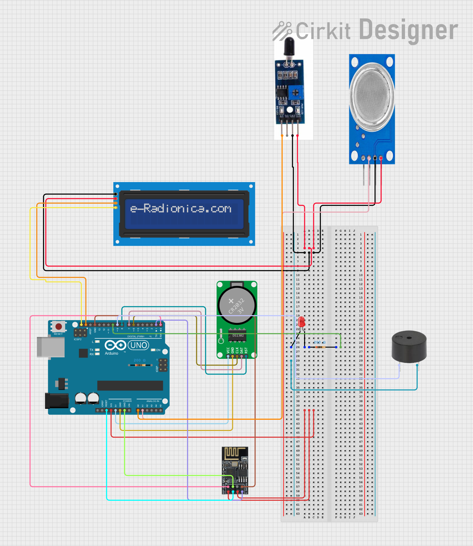
Circuit Documentation
Summary
This circuit integrates various components with an Arduino UNO microcontroller to perform a range of functions, including sensing heat/flame, air quality monitoring, real-time clock tracking, visual display on an LCD, and wireless connectivity via a Wi-Fi module. It also includes a buzzer and an LED for audio-visual signaling. The circuit is powered through the Arduino UNO, which also serves as the central processing unit, running the embedded code to control the components and manage data communication.
Component List
Arduino UNO
- Microcontroller board based on the ATmega328P
- It has 14 digital input/output pins, 6 analog inputs, a 16 MHz quartz crystal, a USB connection, a power jack, an ICSP header, and a reset button.
Heat Flame Sensor
- Sensor module designed to detect flames or fire.
- Outputs both analog and digital signals.
LCD screen 16x2 I2C
- Alphanumeric liquid crystal display with 16 characters per line and 2 lines.
- I2C communication interface for simplified connectivity.
MQ135
- Air quality sensor for detecting a wide range of gases, including NH3, NOx, alcohol, benzene, smoke, and CO2.
RTC-DS1302
- Real-Time Clock module for timekeeping.
- Communicates with the microcontroller via a simple serial interface.
LED: Two Pin (red)
- Basic red LED for indicating status or alerts.
- Requires a current-limiting resistor to prevent damage.
Resistor (200 Ohms)
- Two resistors with a resistance of 200 Ohms each.
- Used for current limiting and voltage division.
Buzzer
- An audio signaling device that can be used to alert users or provide feedback.
Wifi module ESP8266-01
- A Wi-Fi module that offers internet connectivity to the microcontroller.
- Capable of operating in both station and soft-access point mode.
Wiring Details
Arduino UNO
Resetconnected to Wifi module ESP8266-01 Reset3.3Vconnected to Wifi module ESP8266-01 +3V3 and CH-PD Chip power down5Vconnected to RTC-DS1302 VccGNDconnected to multiple components for common groundA0connected to Heat Flame Sensor AOA1connected to MQ135 A0SCLconnected to LCD screen 16x2 I2C SCLSDAconnected to LCD screen 16x2 I2C SDAD10connected to one end of a 200 Ohm ResistorD9connected to Buzzer PIND8connected to RTC-DS1302 RSTD7connected to RTC-DS1302 DATD6connected to RTC-DS1302 CLKD1connected to Wifi module ESP8266-01 TXD0connected to Wifi module ESP8266-01 RX
Heat Flame Sensor
AOconnected to Arduino UNO A0GNDandVCCconnected to common ground and power rails respectively
LCD screen 16x2 I2C
SCLandSDAconnected to Arduino UNO SCL and SDAVCCandGNDconnected to power rails
MQ135
A0connected to Arduino UNO A1VCCandGNDconnected to power rails
RTC-DS1302
Vccconnected to Arduino UNO 5VGNDconnected to common groundRST,DAT,CLKconnected to Arduino UNO D8, D7, D6 respectively
LED: Two Pin (red)
anodeconnected to one end of a 200 Ohm Resistorcathodeconnected to common ground
Resistor (200 Ohms)
- One resistor connected between Arduino UNO D10 and the other end open for connection
- Another resistor connected between LED anode and the other end open for connection
Buzzer
PINconnected to Arduino UNO D9GNDconnected to common ground
Wifi module ESP8266-01
Resetconnected to Arduino UNO Reset+3V3andCH-PD Chip power downconnected to Arduino UNO 3.3VGNDconnected to common groundTXconnected to Arduino UNO D1RXconnected to Arduino UNO D0GPIO0connected to common ground for normal operation
Documented Code
Arduino UNO Code (sketch.ino)
void setup() {
  // put your setup code here, to run once:

}

void loop() {
  // put your main code here, to run repeatedly:

}
Note: The provided code is a template and does not include specific functionality. It needs to be populated with instructions to control and interact with the connected components.