
Circuit Documentation
Summary
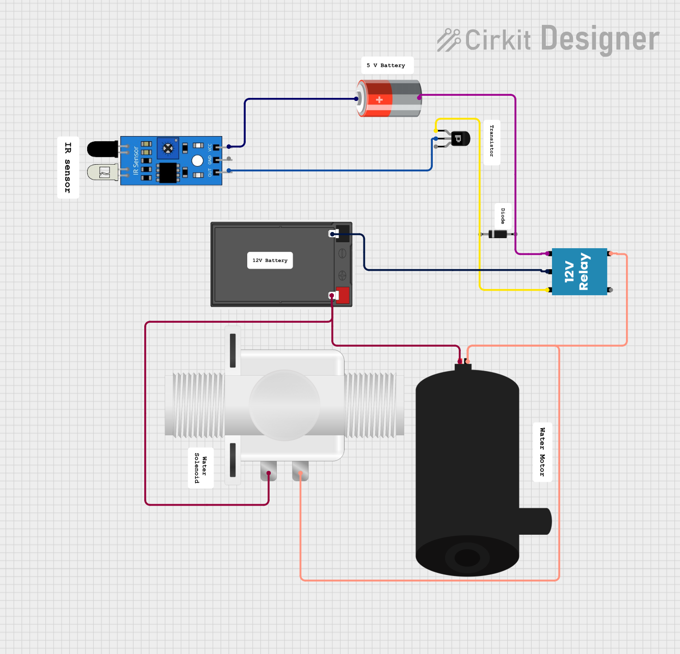
This document provides a detailed overview of a circuit that includes a 5V battery, a 12V relay, a PNP transistor, an IR sensor, a plastic solenoid valve, a water pump, and a diode. The circuit is designed to control the operation of the water pump and solenoid valve based on the input from the IR sensor.
Component List
5V Battery
- Pins: +, -
- Description: Provides a 5V power supply for the circuit.
Battery
- Pins: -, +
- Description: Provides an additional power supply for the circuit.
Plastic Solenoid Valve
- Pins: pin1, pin2
- Description: Controls the flow of liquid in the system.
PNP Transistor (EBC)
- Pins: emitter, base, collector
- Description: Used to switch the relay based on the IR sensor input.
IR Sensor
- Pins: out, gnd, vcc
- Description: Detects infrared signals and provides an output signal.
12V Relay
- Pins: +, -, C, NC, NO
- Description: Controls the connection between the battery and the water pump/solenoid valve.
Water Pump
- Pins: positive, negative
- Description: Pumps water through the system.
Diode
- Pins: cathode, anode
- Description: Ensures current flows in one direction.
Wiring Details
5V Battery
- + is connected to vcc of the IR sensor.
- - is connected to - of the 12V relay.
Battery
- - is connected to C of the 12V relay.
- + is connected to pin1 of the plastic solenoid valve and positive of the water pump.
Plastic Solenoid Valve
- pin1 is connected to + of the battery.
- pin2 is connected to negative of the water pump and NO of the 12V relay.
PNP Transistor (EBC)
- emitter is connected to + of the 12V relay.
- base is connected to out of the IR sensor.
IR Sensor
- out is connected to base of the PNP transistor.
- vcc is connected to + of the 5V battery.
- gnd is connected to - of the 5V battery.
12V Relay
- + is connected to emitter of the PNP transistor.
- - is connected to - of the 5V battery.
- C is connected to - of the battery.
- NO is connected to pin2 of the plastic solenoid valve and negative of the water pump.
Water Pump
- positive is connected to + of the battery.
- negative is connected to pin2 of the plastic solenoid valve and NO of the 12V relay.
Diode
- cathode and anode are not connected in the provided net list.
Code
There is no code provided for this circuit.