
Arduino Mega 2560-Based Smart Greenhouse Monitoring and Control System with Wi-Fi Connectivity
View and Edit Project In Cirkit Designer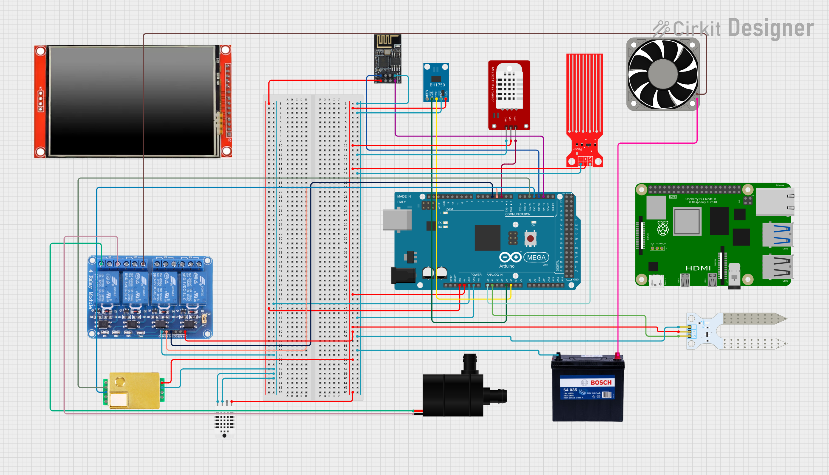
Circuit Documentation
Summary
The circuit is designed to monitor and control an agricultural greenhouse environment. It includes sensors for measuring temperature, humidity, light intensity, water level, and soil moisture. The system uses an Arduino Mega 2560 as the main microcontroller to read sensor data and control actuators such as a water pump and a fan based on environmental conditions. The ESP8266 Wi-Fi module is used for wireless data communication. A relay module is employed to safely switch high-power devices. The circuit is powered by a 12V 200Ah battery, and various components operate at different voltage levels, with voltage regulation provided by the Arduino Mega.
Component List
- Water Level Sensor: Measures the water level in the environment.
- Wifi module ESP8266-01: Provides wireless communication capabilities.
- BH1750: A light intensity sensor that measures lux levels.
- DHT22: A sensor for measuring temperature and humidity.
- Relay 4 Channel 5v: Controls high-power devices such as the water pump and fan.
- MH-Z19B: A CO2 concentration sensor.
- 40 Fan 12v: A fan used to regulate the temperature within the greenhouse.
- Water Pump: Pumps water for irrigation purposes.
- Raspberry Pi 4B: A powerful microcomputer that can be used for advanced data processing and control (not directly interfaced in this circuit).
- Soil Moisture Sensor: Measures the moisture level of the soil.
- Humidity and Temperature Sensor (RHT03): Another sensor for measuring temperature and humidity.
- 12V 200Ah Battery: Provides power to the circuit.
- Arduino Mega 2560: The main microcontroller used for reading sensors and controlling actuators.
- LCD TFT screen ILI9488 HD: A display screen for user interface (not directly interfaced in this circuit).
Wiring Details
Water Level Sensor
- VCC: Connected to Arduino Mega 5V.
- GND: Connected to common ground.
- SIG: Connected to Arduino Mega A0.
Wifi module ESP8266-01
- +3V3: Connected to Arduino Mega 3V3.
- GND: Connected to common ground.
- RX: Connected to Arduino Mega TX1 (D18).
- TX: Connected to Arduino Mega RX1 (D19).
BH1750 Light Sensor
- VCC: Connected to Arduino Mega 5V.
- GND: Connected to common ground.
- SCL: Connected to Arduino Mega A5.
- SDA: Connected to Arduino Mega A4.
DHT22 Temperature and Humidity Sensor
- VCC: Connected to Arduino Mega 5V.
- GND: Connected to common ground.
- DAT: Connected to Arduino Mega D2.
Relay 4 Channel 5v
- VCC: Connected to Arduino Mega 5V.
- GND: Connected to common ground.
- IN1: Connected to Arduino Mega D3.
- IN2: Connected to Arduino Mega D4.
- NO1: Connected to Water Pump GND.
- NO2: Connected to Fan -12V.
- NC1: Connected to Water Pump VCC.
MH-Z19B CO2 Sensor
- Vin: Connected to Arduino Mega 5V.
- GND: Connected to common ground.
- TX: Connected to Arduino Mega RX2 (D17).
- RX: Connected to Arduino Mega TX2 (D16).
40 Fan 12v
- +12V: Connected to 12V 200Ah Battery 12V.
- -12V: Connected to Relay NO2.
Water Pump
- VCC: Connected to Relay NC1.
- GND: Connected to Relay NO1.
Soil Moisture Sensor
- VCC: Connected to Arduino Mega 5V.
- GND: Connected to common ground.
- SIG: Connected to Arduino Mega A1.
12V 200Ah Battery
- 12V: Provides power to the fan.
- GND: Connected to common ground.
Documented Code
Arduino Mega 2560 Code
/*
 * Système de Supervision des Serres Agricoles
 *
 * Ce code lit les données des capteurs connectés à l'Arduino Mega 2560
 * et contrôle les actionneurs (pompe à eau et ventilateur) via un module relais.
 * Les données des capteurs sont envoyées via le module Wi-Fi ESP8266.
 */

#include <Wire.h>
#include <BH1750.h>
#include <DHT.h>
#include <SoftwareSerial.h>

#define DHTPIN 2
#define DHTTYPE DHT22
#define RELAY_PUMP 3
#define RELAY_FAN 4

DHT dht(DHTPIN, DHTTYPE);
BH1750 lightMeter;
SoftwareSerial esp8266(18, 19); // RX, TX

void setup() {
  Serial.begin(9600);
  esp8266.begin(9600);
  dht.begin();
  Wire.begin();
  lightMeter.begin();
  pinMode(RELAY_PUMP, OUTPUT);
  pinMode(RELAY_FAN, OUTPUT);
  digitalWrite(RELAY_PUMP, LOW);
  digitalWrite(RELAY_FAN, LOW);
}

void loop() {
  float h = dht.readHumidity();
  float t = dht.readTemperature();
  uint16_t lux = lightMeter.readLightLevel();
  int waterLevel = analogRead(A0);
  int soilMoisture = analogRead(A1);

  Serial.print("Humidity: ");
  Serial.print(h);
  Serial.print(" %\t");
  Serial.print("Temperature: ");
  Serial.print(t);
  Serial.print(" *C\t");
  Serial.print("Light: ");
  Serial.print(lux);
  Serial.print(" lx\t");
  Serial.print("Water Level: ");
  Serial.print(waterLevel);
  Serial.print(" \t");
  Serial.print("Soil Moisture: ");
  Serial.print(soilMoisture);
  Serial.println();

  // Control the water pump based on water level
  if (waterLevel < 500) {
    digitalWrite(RELAY_PUMP, HIGH);
  } else {
    digitalWrite(RELAY_PUMP, LOW);
  }

  // Control the fan based on temperature
  if (t > 30) {
    digitalWrite(RELAY_FAN, HIGH);
  } else {
    digitalWrite(RELAY_FAN, LOW);
  }

  // Send data to ESP8266
  esp8266.print("Humidity: ");
  esp8266.print(h);
  esp8266.print(" %\t");
  esp8266.print("Temperature: ");
  esp8266.print(t);
  esp8266.print(" *C\t");
  esp8266.print("Light: ");
  esp8266.print(lux);
  esp8266.print(" lx\t");
  esp8266.print("Water Level: ");
  esp8266.print(waterLevel);
  esp8266.print(" \t");
  esp8266.print("Soil Moisture: ");
  esp8266.print(soilMoisture);
  esp8266.println();

  delay(2000);
}
This code is responsible for initializing the sensors and the Wi-Fi module, reading sensor data, controlling the relay module to turn on/off the water pump and fan, and sending sensor data to the ESP8266 module for wireless communication.