Arduino UNO Line Following Robot with L298N Motor Driver and IR Sensors
Circuit Documentation
Summary
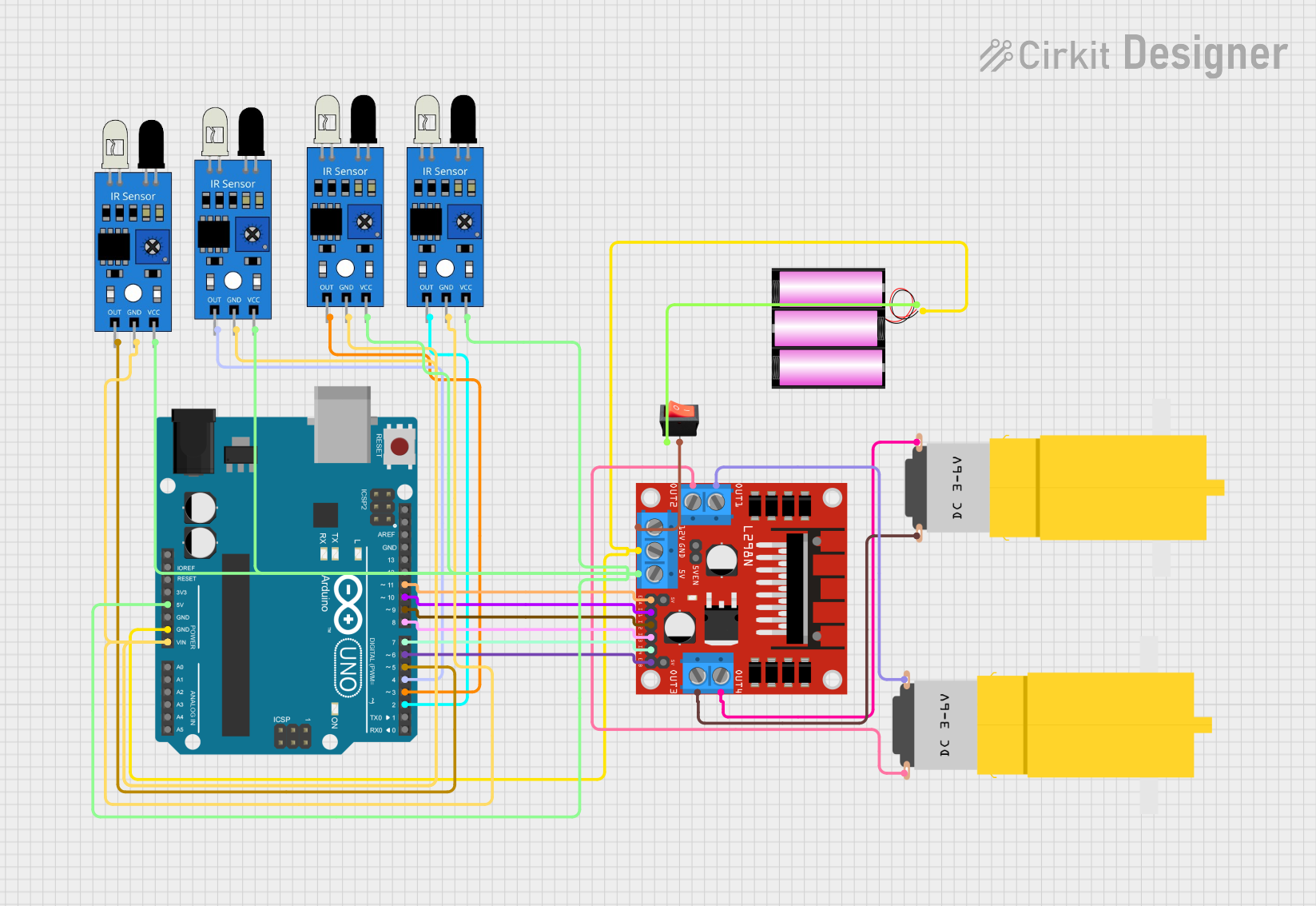
This circuit is designed to control a line-following robot using an Arduino UNO microcontroller, four IR sensors, an L298N DC motor driver, two DC motors, and a 12V battery. The IR sensors are used to detect the line on the ground, and the motor driver controls the motors based on the sensor inputs to steer the robot. A rocker switch is included to control the power supply from the battery to the motor driver.
Component List
Arduino UNO
- Microcontroller board based on the ATmega328P
- It has 14 digital input/output pins, 6 analog inputs, a 16 MHz quartz crystal, a USB connection, a power jack, an ICSP header, and a reset button.
IR Sensors (x4)
- Infrared sensors used for line detection
- Each sensor has an output pin, a ground pin, and a VCC pin for power.
L298N DC Motor Driver
- A module used for controlling up to two DC motors
- It has pins for motor outputs, power supply, ground, and control inputs.
DC Motors (x2)
- Hobbyist yellow gear motors
- Each motor has a VCC and GND pin.
12V Battery
- Power source for the circuit
- It has a positive (+) and a negative (-) terminal.
Rocker Switch
- A switch to control the connection between the battery and the motor driver
- It has an input and an output pin.
Wiring Details
Arduino UNO
- 5V: Connected to the VCC pins of all IR sensors and the 5V pin of the L298N motor driver.
- GND: Connected to the GND pin of the L298N motor driver and the ground pins of all IR sensors.
- Vin: Connected to the ground pins of all IR sensors.
- D2-D11: Control pins connected to the L298N motor driver and the output pins of the IR sensors.
IR Sensors
- VCC: Connected to the 5V output from the Arduino UNO.
- GND: Connected to the ground (GND) on the Arduino UNO.
- OUT: Connected to the digital input pins (D2-D5) on the Arduino UNO.
L298N DC Motor Driver
- 5V: Connected to the 5V output from the Arduino UNO.
- GND: Connected to the ground (GND) on the Arduino UNO.
- 12V: Connected to the output of the rocker switch.
- ENA, ENB: Connected to the PWM output pins (D11, D6) on the Arduino UNO for speed control.
- IN1-IN4: Connected to the digital output pins (D10-D7) on the Arduino UNO for direction control.
- OUT1-OUT4: Connected to the DC motors.
DC Motors
- VCC: Connected to the OUT1 and OUT4 of the L298N motor driver.
- GND: Connected to the OUT2 and OUT3 of the L298N motor driver.
12V Battery
- +: Connected to the input of the rocker switch.
- -: Connected to the ground (GND) of the circuit.
Rocker Switch
- Input: Connected to the positive (+) terminal of the 12V battery.
- Output: Connected to the 12V input of the L298N motor driver.
Documented Code
/*
 * Line Following Robot
 * This code controls a robot that follows a black line using IR sensors
 * to detect the line and an L298N motor driver to control the motors.
 * Sensor 2 and 3 should be inside the black line, while sensor 1 and 4
 * should be outside the black line.
 */

// Pin definitions
const int irSensor1 = 4;
const int irSensor2 = 5;
const int irSensor3 = 2;
const int irSensor4 = 3;
const int motorIn1 = 10;
const int motorIn2 = 9;
const int motorIn3 = 8;
const int motorIn4 = 7;
const int motorEnA = 11;
const int motorEnB = 6;

void setup() {
  // Initialize IR sensor pins as inputs
  pinMode(irSensor1, INPUT);
  pinMode(irSensor2, INPUT);
  pinMode(irSensor3, INPUT);
  pinMode(irSensor4, INPUT);

  // Initialize motor control pins as outputs
  pinMode(motorIn1, OUTPUT);
  pinMode(motorIn2, OUTPUT);
  pinMode(motorIn3, OUTPUT);
  pinMode(motorIn4, OUTPUT);
  pinMode(motorEnA, OUTPUT);
  pinMode(motorEnB, OUTPUT);

  // Start with motors stopped
  stopMotors();
}

void loop() {
  // Read IR sensor values
  int sensor1 = digitalRead(irSensor1);
  int sensor2 = digitalRead(irSensor2);
  int sensor3 = digitalRead(irSensor3);
  int sensor4 = digitalRead(irSensor4);

  // Determine robot movement based on sensor values
  if (sensor2 == LOW && sensor3 == LOW) {
    // Move forward
    moveForward();
  } else if (sensor1 == HIGH) {
    // Turn right
    turnRight();
  } else if (sensor4 == HIGH) {
    // Turn left
    turnLeft();
  } else {
    // Stop if no clear path
    stopMotors();
  }
}

void moveForward() {
  digitalWrite(motorIn1, HIGH);
  digitalWrite(motorIn2, LOW);
  digitalWrite(motorIn3, HIGH);
  digitalWrite(motorIn4, LOW);
  analogWrite(motorEnA, 255);
  analogWrite(motorEnB, 255);
}

void turnRight() {
  digitalWrite(motorIn1, LOW);
  digitalWrite(motorIn2, HIGH);
  digitalWrite(motorIn3, HIGH);
  digitalWrite(motorIn4, LOW);
  analogWrite(motorEnA, 255);
  analogWrite(motorEnB, 255);
}

void turnLeft() {
  digitalWrite(motorIn1, HIGH);
  digitalWrite(motorIn2, LOW);
  digitalWrite(motorIn3, LOW);
  digitalWrite(motorIn4, HIGH);
  analogWrite(motorEnA, 255);
  analogWrite(motorEnB, 255);
}

void stopMotors() {
  digitalWrite(motorIn1, LOW);
  digitalWrite(motorIn2, LOW);
  digitalWrite(motorIn3, LOW);
  digitalWrite(motorIn4, LOW);
  analogWrite(motorEnA, 0);
  analogWrite(motorEnB, 0);
}
This code is responsible for reading the IR sensor inputs and controlling the motors accordingly to follow a line. The setup() function initializes the sensor and motor control pins, and the loop() function continuously reads the sensor values to determine the robot's movement. The robot moves forward when both middle sensors detect the line, turns right or left when the outer sensors detect the line, and stops when no clear path is detected. The moveForward(), turnRight(), turnLeft(), and stopMotors() functions control the motor driver's inputs to achieve the desired movement.