Cirkit Designer
Your all-in-one circuit design IDE
Home /
Project Documentation
Arduino-Controlled Dual Stepper Motor System with Rotary Encoder Feedback

Circuit Documentation
Summary
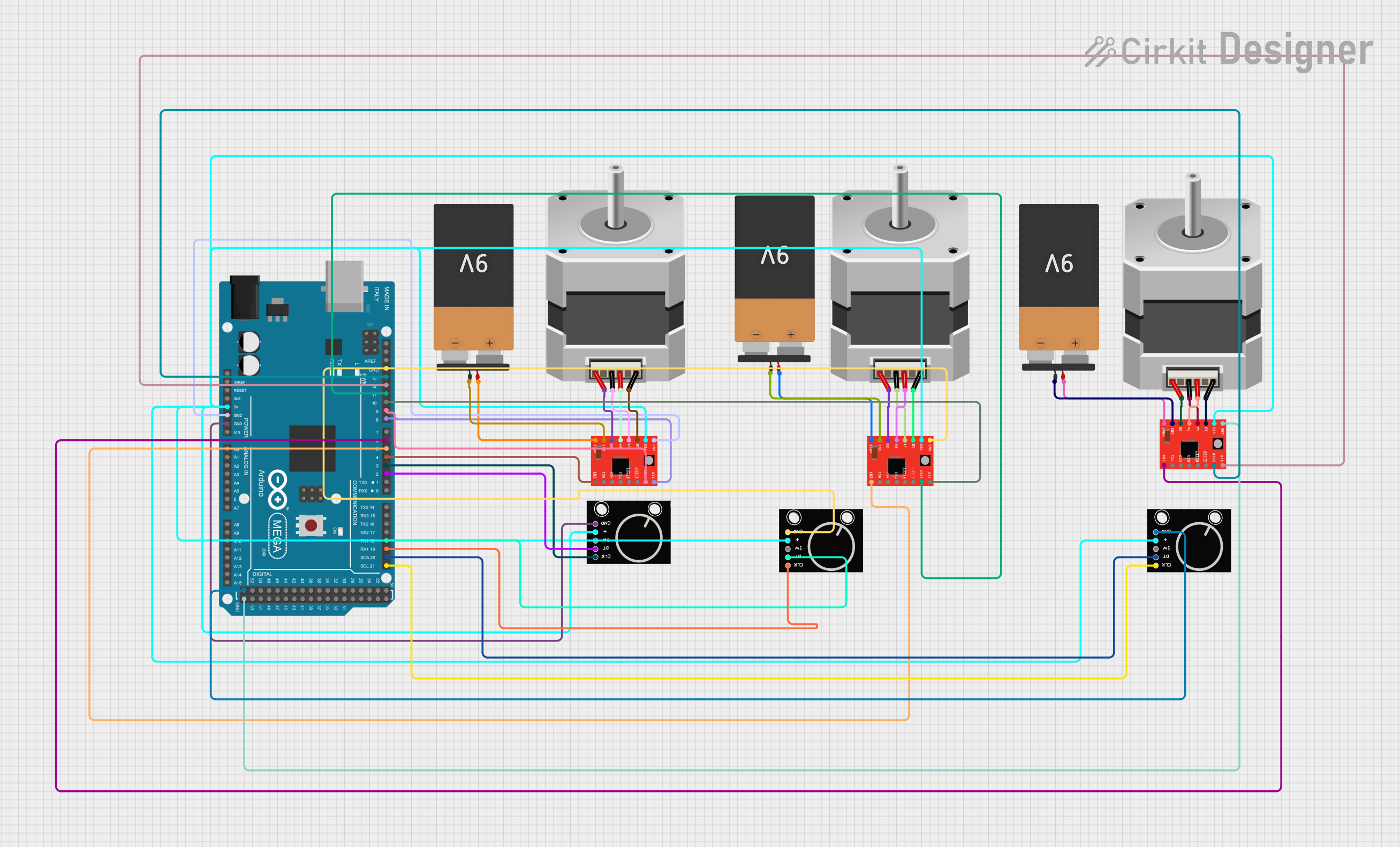
This circuit primarily consists of an Arduino Mega 2560 microcontroller interfaced with multiple A4988 Stepper Motor Drivers to control several bipolar stepper motors. Additionally, rotary encoders are included for user input. The circuit is powered by 9V batteries, with connections to the motor drivers and rotary encoders. The Arduino Mega 2560 manages the control signals for the stepper motor drivers and processes the signals from the rotary encoders.
Component List
Arduino Mega 2560
- Microcontroller board based on the ATmega2560
- Offers 54 digital input/output pins (of which 15 can be used as PWM outputs), 16 analog inputs, 4 UARTs (hardware serial ports), a 16 MHz crystal oscillator, a USB connection, a power jack, an ICSP header, and a reset button.
A4988 Stepper Motor Driver (Red)
- Module for driving bipolar stepper motors
- Simple step and direction control interface
- Five different step resolutions: full-step, half-step, quarter-step, eighth-step, and sixteenth-step
- Adjustable current control
Stepper Motor (Bipolar)
- A motor with a pair of electromagnetic coils or phases that can be directionally controlled for precision movements
Battery 9V
- Standard 9V battery used to provide power to the circuit
Rotary Encoder
- An input device that provides a way to measure position, velocity, and acceleration by converting rotational mechanical displacements into electrical signals
Wiring Details
Arduino Mega 2560
D6 PWM- Connected to ENABLE pin of one A4988 Stepper Motor DriverD13 PWM- Connected to STEP pin of the same A4988 Stepper Motor DriverD12 PWM- Connected to DIR pin of the same A4988 Stepper Motor Driver5V- Supplies power to VDD pins of all A4988 Stepper Motor Drivers and Rotary EncodersGND- Common ground for the circuitD2 PWM,D3 PWM- Connected to DT and CLK pins of one Rotary EncoderD21/SCL,D20/SDA- Connected to CLK and DT pins of another Rotary EncoderD19/RX1,D18/TX1- Connected to CLK and DT pins of the third Rotary EncoderD4 PWM,D5 PWM,D8 PWM,D9 PWM,D10 PWM,D11 PWM- Control pins for additional A4988 Stepper Motor Drivers
A4988 Stepper Motor Driver (Red)
ENABLE,STEP,DIR- Control pins connected to the Arduino Mega 2560VMOT- Connected to VCC of a 9V BatteryGND- Connected to GND of a 9V Battery2B,2A,1A,1B- Connected to corresponding pins A, B, C, D of a Stepper Motor (Bipolar)VDD- Connected to 5V supply from the Arduino Mega 2560
Stepper Motor (Bipolar)
A,B,C,D- Connected to corresponding pins 2B, 2A, 1A, 1B of an A4988 Stepper Motor Driver
Battery 9V
VCC- Supplies power to VMOT pins of A4988 Stepper Motor DriversGND- Common ground for the circuit
Rotary Encoder
+- Connected to 5V supply from the Arduino Mega 2560GND- Common ground for the circuitSW,DT,CLK- Signal pins connected to the Arduino Mega 2560
Documented Code
sketch.ino
void setup() {
  // put your setup code here, to run once:

}

void loop() {
  // put your main code here, to run repeatedly:

}
documentation.txt
The code file documentation.txt is empty and does not contain any additional information.