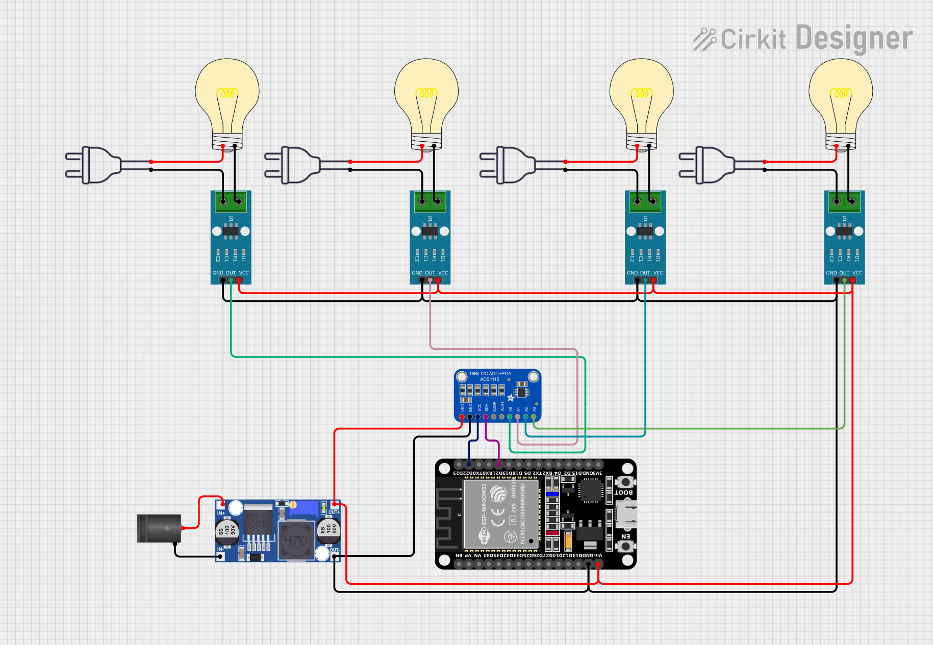
ESP32-Controlled Smart Lighting System with Power Monitoring

Circuit Documentation
Summary
The circuit described by the provided inputs is a monitoring system that utilizes an ESP32 microcontroller to interface with multiple ACS712 current sensors through an Adafruit ADS1115 16-bit I2C ADC (Analog-to-Digital Converter). The ESP32 reads current measurements from the ACS712 sensors and communicates via I2C with the ADS1115. The circuit is powered through a 2.1mm DC Barrel Jack, which is connected to a Buck converter to step down the voltage to a level suitable for the microcontroller and sensors. Additionally, there are several bulbs in the circuit, each connected to a corresponding ACS712 sensor to presumably act as a load for current measurement.
Component List
2.1mm DC Barrel Jack
- Description: A connector for a DC power supply.
- Pins: switch, sleeve, center
Buck Converter
- Description: A DC-DC converter that steps down voltage from a higher level to a lower level.
- Pins: IN+, IN-, OUT+, OUT-
Adafruit ADS1115 16Bit I2C ADC
- Description: A high precision, 16-bit analog-to-digital converter with I2C interface.
- Pins: VDD, GND, SCL, SDA, ADDR, ALERT, AIN0, AIN1, AIN2, AIN3
ESP32 (30 pin)
- Description: A microcontroller with Wi-Fi and Bluetooth capabilities, featuring a wide range of GPIO pins.
- Pins: EN, VP, VN, D34, D35, D32, D33, D25, D26, D27, D14, D12, D13, GND, Vin, D23, D22, TX0, RX0, D21, D19, D18, D5, TX2, RX2, D4, D2, D15, 3V3
ACS712 Current Sensor 5A 20A 30A
- Description: A hall-effect-based linear current sensor capable of measuring both AC and DC currents.
- Pins: 1, 2, GND, OUT, VCC
Bulb
- Description: An electrical device used to create artificial light by the use of an electric current.
- Pins: positive, negative
Power 220V
- Description: Represents the main AC power supply.
- Pins: hot wire, neutral wire
Wiring Details
2.1mm DC Barrel Jack
- center: Connected to Buck converter IN+
- sleeve: Connected to Buck converter IN-
Buck Converter
- IN+: Connected to 2.1mm DC Barrel Jack center
- IN-: Connected to 2.1mm DC Barrel Jack sleeve
- OUT+: Connected to VDD of Adafruit ADS1115, VCC of all ACS712 sensors, and Vin of ESP32
- OUT-: Connected to GND of Adafruit ADS1115, GND of all ACS712 sensors, and GND of ESP32
Adafruit ADS1115 16Bit I2C ADC
- VDD: Connected to Buck converter OUT+
- GND: Connected to Buck converter OUT-
- SCL: Connected to ESP32 D22
- SDA: Connected to ESP32 D21
- AIN0: Connected to ACS712 sensor OUT (instance a7cf3282)
- AIN1: Connected to ACS712 sensor OUT (instance 342206ec)
- AIN2: Connected to ACS712 sensor OUT (instance 868bada3)
- AIN3: Connected to ACS712 sensor OUT (instance cac56321)
ESP32 (30 pin)
- Vin: Connected to Buck converter OUT+
- GND: Connected to Buck converter OUT-
- D22: Connected to SCL of Adafruit ADS1115
- D21: Connected to SDA of Adafruit ADS1115
ACS712 Current Sensor 5A 20A 30A (Multiple Instances)
- VCC: Connected to Buck converter OUT+
- GND: Connected to Buck converter OUT-
- OUT: Connected to corresponding AINx on Adafruit ADS1115
- 1: Connected to negative of corresponding Bulb
- 2: Connected to hot wire of corresponding Power 220V
Bulb (Multiple Instances)
- positive: Connected to neutral wire of corresponding Power 220V
- negative: Connected to pin 1 of corresponding ACS712 sensor
Power 220V (Multiple Instances)
- hot wire: Connected to pin 2 of corresponding ACS712 sensor
- neutral wire: Connected to positive of corresponding Bulb
Documented Code
No code was provided for the microcontrollers in the circuit. Therefore, this section is not applicable for the current documentation.