
Smart DC Motor Control System with Relay and Capacitive Sensors
View and Edit Project In Cirkit Designer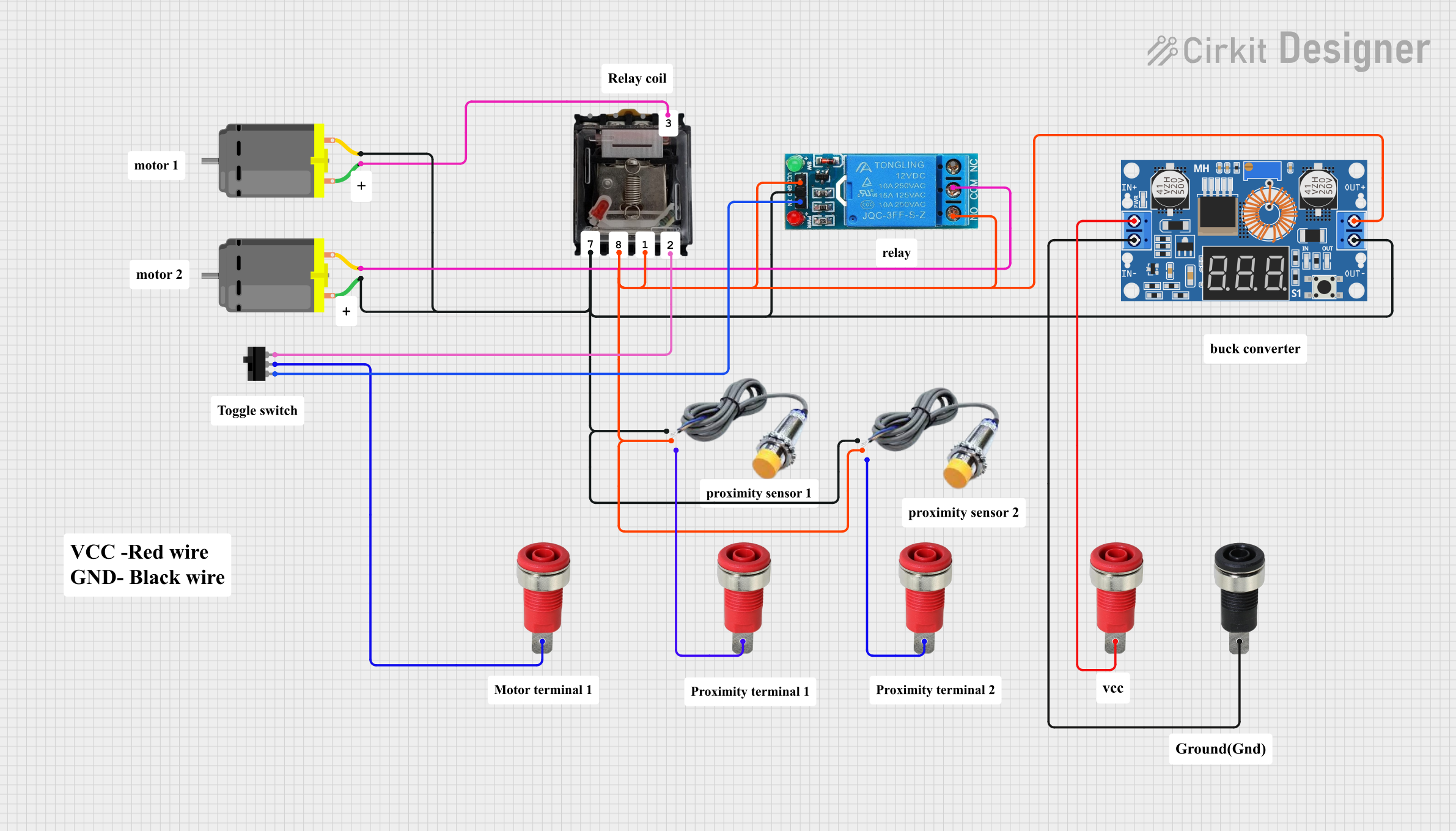
Circuit Documentation
Summary
This document provides a detailed overview of a circuit that includes various components such as relays, DC motors, toggle switches, capacitive sensors, and a DC buck step-down converter. The circuit is designed to control the operation of DC motors using relays and sensors, with power regulation provided by a buck converter.
Component List
Relay Omron MK2P-N
- Pins: 6, 5, 4, 3, 7, 8, 1, 2
- Description: General-purpose relay used for switching applications.
12V SINGLE CHANNEL RELAY
- Pins: NC, COM, NO, IN, GND, VCC
- Description: Single-channel relay module for controlling high voltage devices.
DC Motor
- Pins: pin 1, pin 2
- Description: Standard DC motor for mechanical movement.
Toggle Switch
- Pins: L1, COM, L2
- Description: Switch used to toggle the state of the circuit.
Capacitive Sensor
- Pins: GND, VCC, SIGNAL
- Description: Sensor used to detect the presence of a conductive object.
Red Panel Mount 4mm Banana Socket
- Pins: Red_Pin
- Description: Red banana socket for power connections.
Black Panel Mount 4mm Banana Socket
- Pins: Black_Pin
- Description: Black banana socket for ground connections.
XL4015 5A DC Buck Step-down
- Pins: Output +, Output -, Input +, Input -
- Description: DC-DC buck converter for voltage regulation.
Wiring Details
Relay Omron MK2P-N
- Pin 3 is connected to pin 1 of a DC Motor.
- Pin 7 is connected to:
- GND of the 12V SINGLE CHANNEL RELAY
- GND of a Capacitive Sensor
- pin 2 of a DC Motor
- Output - of the XL4015 5A DC Buck Step-down
- GND of another Capacitive Sensor
- pin 1 of another DC Motor
- Pin 8 is connected to:
- NO of the 12V SINGLE CHANNEL RELAY
- VCC of the 12V SINGLE CHANNEL RELAY
- VCC of a Capacitive Sensor
- Output + of the XL4015 5A DC Buck Step-down
- VCC of another Capacitive Sensor
- Pin 2 is connected to L2 of the Toggle Switch.
12V SINGLE CHANNEL RELAY
- GND is connected to:
- Pin 7 of the Relay Omron MK2P-N
- GND of a Capacitive Sensor
- pin 2 of a DC Motor
- Output - of the XL4015 5A DC Buck Step-down
- GND of another Capacitive Sensor
- pin 1 of another DC Motor
- NO is connected to:
- Pin 8 of the Relay Omron MK2P-N
- VCC of the 12V SINGLE CHANNEL RELAY
- VCC of a Capacitive Sensor
- Output + of the XL4015 5A DC Buck Step-down
- VCC of another Capacitive Sensor
- COM is connected to pin 2 of a DC Motor.
- IN is connected to L1 of the Toggle Switch.
DC Motor
- pin 1 of one motor is connected to pin 3 of the Relay Omron MK2P-N.
- pin 2 of the same motor is connected to:
- GND of the 12V SINGLE CHANNEL RELAY
- Pin 7 of the Relay Omron MK2P-N
- GND of a Capacitive Sensor
- Output - of the XL4015 5A DC Buck Step-down
- GND of another Capacitive Sensor
- pin 1 of another DC Motor
- pin 1 of another motor is connected to Pin 7 of the Relay Omron MK2P-N.
- pin 2 of the same motor is connected to COM of the 12V SINGLE CHANNEL RELAY.
Toggle Switch
- L2 is connected to Pin 2 of the Relay Omron MK2P-N.
- L1 is connected to IN of the 12V SINGLE CHANNEL RELAY.
- COM is connected to Red_Pin of a Red Panel Mount 4mm Banana Socket.
Capacitive Sensor
- GND of one sensor is connected to:
- GND of the 12V SINGLE CHANNEL RELAY
- Pin 7 of the Relay Omron MK2P-N
- pin 2 of a DC Motor
- Output - of the XL4015 5A DC Buck Step-down
- GND of another Capacitive Sensor
- pin 1 of another DC Motor
- VCC of the same sensor is connected to:
- NO of the 12V SINGLE CHANNEL RELAY
- Pin 8 of the Relay Omron MK2P-N
- VCC of the 12V SINGLE CHANNEL RELAY
- Output + of the XL4015 5A DC Buck Step-down
- VCC of another Capacitive Sensor
- SIGNAL of the same sensor is connected to Red_Pin of a Red Panel Mount 4mm Banana Socket.
- GND of another sensor is connected to:
- GND of the 12V SINGLE CHANNEL RELAY
- Pin 7 of the Relay Omron MK2P-N
- pin 2 of a DC Motor
- Output - of the XL4015 5A DC Buck Step-down
- GND of another Capacitive Sensor
- pin 1 of another DC Motor
- VCC of the same sensor is connected to:
- NO of the 12V SINGLE CHANNEL RELAY
- Pin 8 of the Relay Omron MK2P-N
- VCC of the 12V SINGLE CHANNEL RELAY
- Output + of the XL4015 5A DC Buck Step-down
- VCC of another Capacitive Sensor
- SIGNAL of the same sensor is connected to Red_Pin of another Red Panel Mount 4mm Banana Socket.
Red Panel Mount 4mm Banana Socket
- Red_Pin of one socket is connected to COM of the Toggle Switch.
- Red_Pin of another socket is connected to SIGNAL of a Capacitive Sensor.
- Red_Pin of another socket is connected to SIGNAL of another Capacitive Sensor.
- Red_Pin of another socket is connected to Input + of the XL4015 5A DC Buck Step-down.
Black Panel Mount 4mm Banana Socket
- Black_Pin is connected to Input - of the XL4015 5A DC Buck Step-down.
XL4015 5A DC Buck Step-down
- Output - is connected to:
- GND of the 12V SINGLE CHANNEL RELAY
- Pin 7 of the Relay Omron MK2P-N
- GND of a Capacitive Sensor
- pin 2 of a DC Motor
- GND of another Capacitive Sensor
- pin 1 of another DC Motor
- Output + is connected to:
- NO of the 12V SINGLE CHANNEL RELAY
- Pin 8 of the Relay Omron MK2P-N
- VCC of the 12V SINGLE CHANNEL RELAY
- VCC of a Capacitive Sensor
- VCC of another Capacitive Sensor
- Input + is connected to Red_Pin of a Red Panel Mount 4mm Banana Socket.
- Input - is connected to Black_Pin of the Black Panel Mount 4mm Banana Socket.
Code
No microcontroller code is provided for this circuit.