Arduino UNO Based Multi-Flame Sensor Detection System
Circuit Documentation
Summary of the Circuit
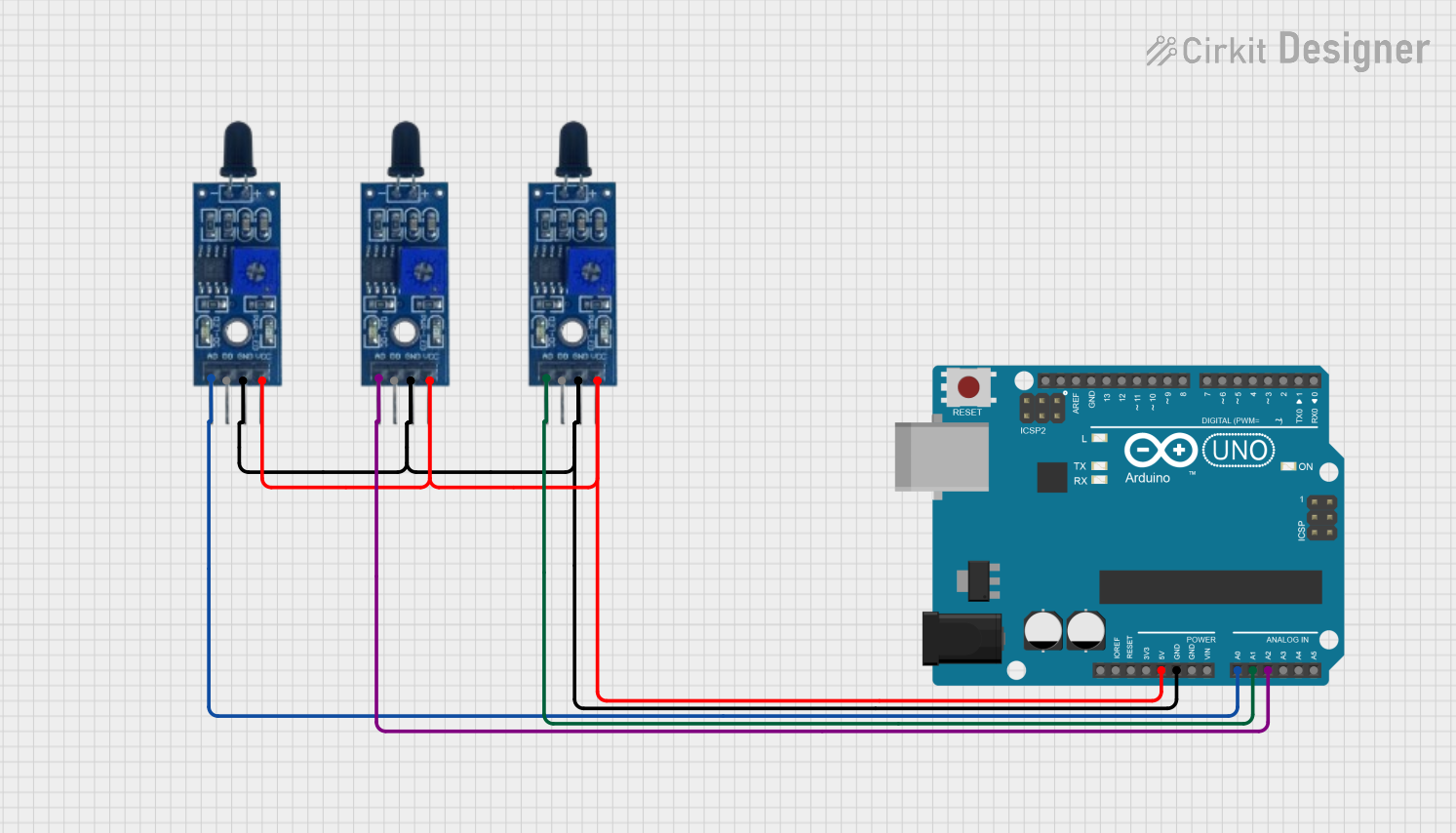
This circuit consists of an Arduino UNO microcontroller board and three identical Flame Sensors. The Arduino UNO is used as the central processing unit to read signals from the Flame Sensors and execute embedded code to perform specific tasks based on the sensor inputs. Each Flame Sensor is capable of detecting a flame and providing both digital and analog outputs. The sensors are powered by the 5V output from the Arduino UNO and are grounded to the same board. The analog outputs from the Flame Sensors are connected to three separate analog input pins on the Arduino UNO for individual flame detection readings.
Component List
Arduino UNO
- Description: A microcontroller board based on the ATmega328P.
- Pins: UNUSED, IOREF, Reset, 3.3V, 5V, GND, Vin, A0-A5, SCL, SDA, AREF, D0-D13.
- Purpose: Acts as the central processing unit for the circuit, reading sensor data and executing the embedded code.
Flame Sensor
- Description: A sensor module capable of detecting a flame or a light source of a wavelength in the range of 760nm to 1100 nm.
- Pins: VCC, GND, D0, A0.
- Purpose: To detect the presence of a flame and provide digital or analog signals to the Arduino UNO.
Wiring Details
Arduino UNO
- 5V: Connected to the VCC pins of all Flame Sensors to provide power.
- GND: Connected to the GND pins of all Flame Sensors to complete the power circuit.
- A0: Connected to the A0 pin of the first Flame Sensor for analog signal reading.
- A1: Connected to the A0 pin of the second Flame Sensor for analog signal reading.
- A2: Connected to the A0 pin of the third Flame Sensor for analog signal reading.
Flame Sensor 1
- VCC: Connected to the 5V pin of the Arduino UNO.
- GND: Connected to the GND pin of the Arduino UNO.
- A0: Connected to the A0 pin of the Arduino UNO for analog signal output.
Flame Sensor 2
- VCC: Connected to the 5V pin of the Arduino UNO.
- GND: Connected to the GND pin of the Arduino UNO.
- A0: Connected to the A1 pin of the Arduino UNO for analog signal output.
Flame Sensor 3
- VCC: Connected to the 5V pin of the Arduino UNO.
- GND: Connected to the GND pin of the Arduino UNO.
- A0: Connected to the A2 pin of the Arduino UNO for analog signal output.
Documented Code
The code for the Arduino UNO is written in the Arduino programming language (based on C/C++) and is used to initialize the microcontroller and repeatedly execute the main logic in a loop.
void setup() {
  // put your setup code here, to run once:

}

void loop() {
  // put your main code here, to run repeatedly:

}
File Name: sketch.ino
The code provided is a template and does not contain any specific logic for interacting with the Flame Sensors. To complete the circuit functionality, the user should add code within the setup() function to initialize the sensor pins and within the loop() function to read the analog values from the sensors and act upon them accordingly.