
Arduino UNO and ADS1220-Based Precision Voltage Measurement System
View and Edit Project In Cirkit Designer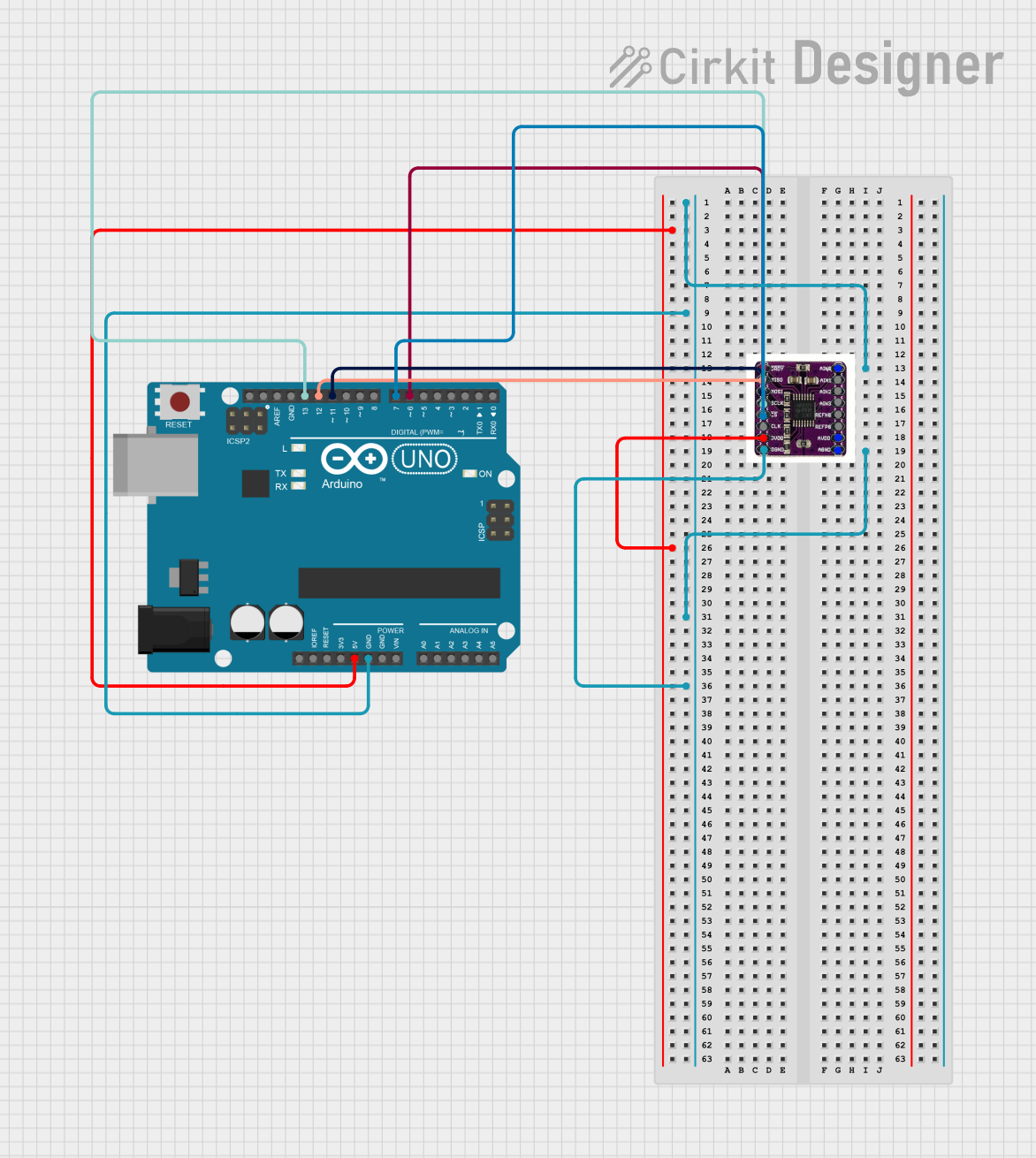
Circuit Documentation
Summary
This circuit involves an Arduino UNO microcontroller interfacing with an ADS1220 analog-to-digital converter (ADC). The Arduino UNO reads analog signals from the ADS1220 and processes them. The communication between the Arduino and the ADS1220 is facilitated through the SPI protocol.
Component List
Arduino UNO
- Description: A microcontroller board based on the ATmega328P.
- Pins: UNUSED, IOREF, Reset, 3.3V, 5V, GND, Vin, A0, A1, A2, A3, A4, A5, SCL, SDA, AREF, D13, D12, D11, D10, D9, D8, D7, D6, D5, D4, D3, D2, D1, D0
ADS1220
- Description: A 24-bit ADC with an integrated low-noise programmable gain amplifier.
- Pins: AIN0, AIN1, AIN3, REFN0, DRDY, MISO, MOSI, SCLK, CS, CLK, DVDD, DGND, AGND, AVDD, REFP0
Wiring Details
Arduino UNO
- 5V: Connected to DVDD of ADS1220
- GND: Connected to AGND, DGND, and AIN0 of ADS1220
- D13: Connected to SCLK of ADS1220
- D12: Connected to MISO of ADS1220
- D11: Connected to MOSI of ADS1220
- D7: Connected to CS of ADS1220
- D6: Connected to DRDY of ADS1220
ADS1220
- DVDD: Connected to 5V of Arduino UNO
- AGND: Connected to GND of Arduino UNO
- DGND: Connected to GND of Arduino UNO
- AIN0: Connected to GND of Arduino UNO
- SCLK: Connected to D13 of Arduino UNO
- MISO: Connected to D12 of Arduino UNO
- MOSI: Connected to D11 of Arduino UNO
- CS: Connected to D7 of Arduino UNO
- DRDY: Connected to D6 of Arduino UNO
Code Documentation
Arduino UNO Code
#include <Protocentral_ADS1220.h>

const float VREF = 5;       // Reference voltage in volts
const int32_t ADC_MAX = 8388607; // Max value for 24-bit ADC (2^23 - 1)
const int Gain = 1;           // Gain setting (adjust if different)
Protocentral_ADS1220 myADC; // Create an instance of the ADS1220 class

void setup() {
  Serial.begin(9600);          // Initialize Serial communication
  myADC.begin(7, 6);           // Initialize the ADS1220 with CS_PIN and DRDY_PIN
}

void loop() {
  myADC.set_conv_mode_continuous(); // Set the ADC to continuous mode conversion
  myADC.select_mux_channels(MUX_SE_CH0);    // Choose channel 0 to read (adjust as needed)

  int32_t rawADC = myADC.Read_WaitForData(); // Read ADC data registers

  float voltage = (rawADC * VREF) / (Gain * ADC_MAX);

  Serial.println(voltage);                    // Print read data
  //delay(10);
}
ADS1220 Code
void setup() {
  // put your setup code here, to run once:
}

void loop() {
  // put your main code here, to run repeatedly:
}
This documentation provides a comprehensive overview of the circuit, including the components used, their wiring details, and the code running on the microcontrollers.