
Circuit Documentation
Summary of the Circuit
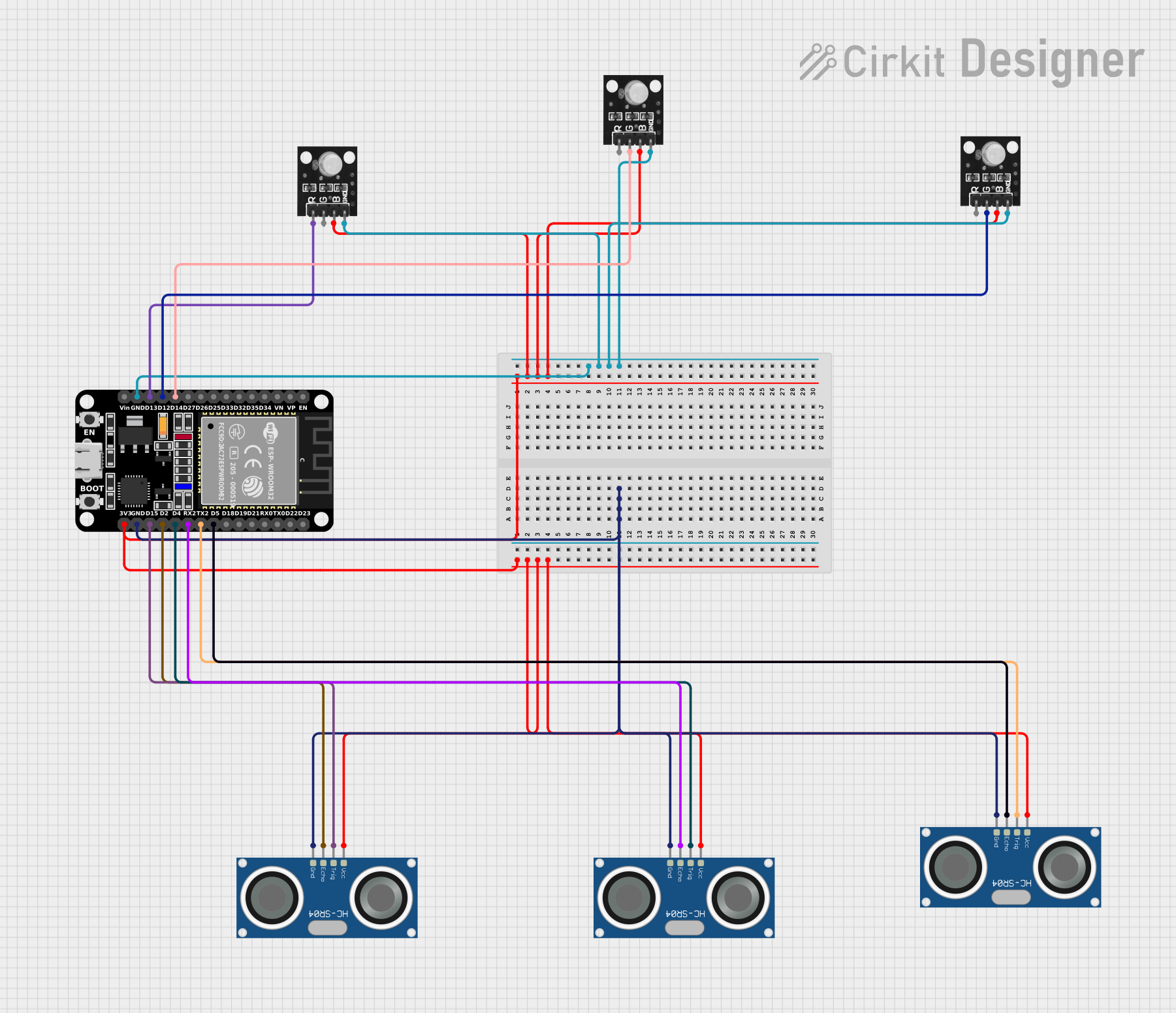
This circuit is designed to interface an ESP32 microcontroller with multiple RGB LED modules and HC-SR04 ultrasonic sensors. The ESP32 controls the RGB LEDs and reads distance measurements from the ultrasonic sensors. The LEDs are individually controlled, with each color channel connected to a specific GPIO pin on the ESP32. The ultrasonic sensors are used to measure distances, with their trigger and echo pins connected to different GPIO pins on the ESP32. The ground pins of all components are connected to the ESP32's ground, and the power pins are connected to the ESP32's 3.3V output, providing the necessary power for the sensors and LEDs.
Component List
ESP32 (30 pin)
- Description: A microcontroller with Wi-Fi and Bluetooth capabilities, featuring a wide range of GPIO pins.
- Pins: EN, VP, VN, D34, D35, D32, D33, D25, D26, D27, D14, D12, D13, GND, Vin, D23, D22, TX0, RX0, D21, D19, D18, D5, TX2, RX2, D4, D2, D15, 3V3
RGB Led module
- Description: A module with a red, green, and blue LED that can be individually controlled.
- Pins: +VCC Red, +VCC Green, +VCC Blue, GND
HC-SR04 Ultrasonic Sensor
- Description: A sensor for measuring distances using ultrasonic waves, with separate trigger and echo pins.
- Pins: VCC, TRIG, ECHO, GND
Wiring Details
ESP32 (30 pin)
- D14: Connected to the green channel of one RGB LED module.
- D12: Connected to the green channel of another RGB LED module.
- D13: Connected to the red channel of an RGB LED module.
- GND: Common ground for all components.
- D5, TX2, RX2, D4, D2, D15: Connected to the ECHO and TRIG pins of the HC-SR04 Ultrasonic Sensors.
- 3V3: Powers all RGB LED modules and HC-SR04 Ultrasonic Sensors.
RGB Led module
- +VCC Red: Connected to D13 on the ESP32.
- +VCC Green: Connected to D14 or D12 on the ESP32 (depending on the instance).
- +VCC Blue: Powered by the 3V3 pin on the ESP32.
- GND: Connected to the GND pin on the ESP32.
HC-SR04 Ultrasonic Sensor
- VCC: Powered by the 3V3 pin on the ESP32.
- TRIG: Connected to TX2, D4, or D15 on the ESP32 (depending on the instance).
- ECHO: Connected to D5, RX2, or D2 on the ESP32 (depending on the instance).
- GND: Connected to the GND pin on the ESP32.
Documented Code
No code has been provided for the microcontrollers in the circuit. The documentation of the code would typically include a description of the functionality, setup, and main loop, along with comments explaining the purpose of each function and variable. Since no code is available, this section cannot be completed. If code becomes available, it should be documented here following best practices for code documentation and readability.