Arduino UNO Controlled Touch-Activated LED Circuit
Circuit Documentation
Summary of the Circuit
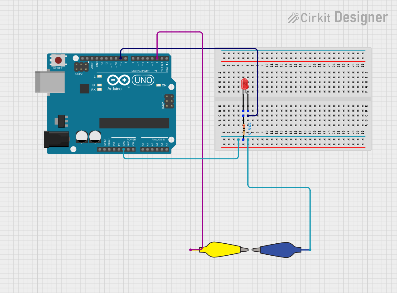
This circuit is designed around an Arduino UNO microcontroller and includes a simple LED circuit with a resistor for current limiting. The LED is controlled by the Arduino, which turns it on when a metal contact connected to another pin is touched, creating a connection to ground. The circuit uses alligator clip cables for connections and includes a pull-up resistor configuration for the metal contact input.
Component List
Arduino UNO
- Description: A microcontroller board based on the ATmega328P.
- Purpose: Acts as the central controller for the circuit, driving the LED and reading the state of the metal contact.
Resistor
- Description: A passive two-terminal electrical component that implements electrical resistance as a circuit element.
- Value: 220 Ohms
- Purpose: Limits the current flowing through the LED to prevent damage.
LED: Two Pin (red)
- Description: A basic red light-emitting diode.
- Purpose: Serves as an indicator light that is controlled by the Arduino.
12978-alligator_clip_cable_half-yellow
- Description: A yellow alligator clip cable used for making temporary electrical connections.
- Purpose: Used to connect the metal contact to the Arduino.
12978-alligator_clip_cable_half-blue
- Description: A blue alligator clip cable used for making temporary electrical connections.
- Purpose: Used to connect the ground of the Arduino to the resistor.
Wiring Details
Arduino UNO
- D9: Connected to the anode of the LED.
- GND: Connected to pin 2 of the Resistor and the Pin of the blue alligator clip cable.
- D2: Connected to the Pin of the yellow alligator clip cable (metal contact).
Resistor
- Pin 1: Connected to the cathode of the LED.
- Pin 2: Connected to the GND of the Arduino and the Pin of the blue alligator clip cable.
LED: Two Pin (red)
- Anode: Connected to D9 of the Arduino.
- Cathode: Connected to pin 1 of the Resistor.
12978-alligator_clip_cable_half-yellow
- Pin: Connected to D2 of the Arduino.
- Alligator: Intended to be connected to a metal contact.
12978-alligator_clip_cable_half-blue
- Pin: Connected to GND of the Arduino and pin 2 of the Resistor.
- Alligator: Intended to be connected to a common ground point or the cathode of the LED.
Documented Code
// Declaration of pins
const int ledPin = 9;       // LED pin
const int metalPin = 2;     // Pin for metal contact
const int resistorValue = 220; // Value of the resistor

void setup() {
  // Initialize the LED pin as an output
  pinMode(ledPin, OUTPUT);

  // Initialize the metal pin as an input with internal pull-up
  pinMode(metalPin, INPUT_PULLUP);

  // Turn off the LED by default
  digitalWrite(ledPin, LOW);
}

void loop() {
  // Read the state of the metal contact
  int metalContact = digitalRead(metalPin);

  // If metal touches the conductor (contact with GND)
  if (metalContact == LOW) {
    // Turn on the LED
    digitalWrite(ledPin, HIGH);
  } else {
    // Turn off the LED
    digitalWrite(ledPin, LOW);
  }
}
File Name: sketch.ino
This code is written for the Arduino UNO and controls an LED based on the state of a metal contact. The LED is connected to pin D9 and is turned on when the metal contact connected to pin D2 is touched, pulling the pin to ground. The internal pull-up resistor on pin D2 ensures that the pin is normally high when the contact is not touched.