
Circuit Documentation
Summary
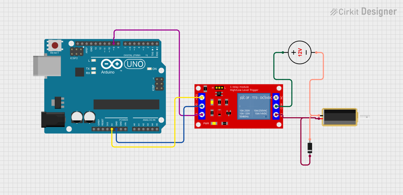
This circuit is designed to control a solenoid using an Arduino UNO and a 1 Channel 5V Relay Module. The solenoid is activated and deactivated alternately with a specified delay, allowing for controlled operation. The relay module acts as an interface between the Arduino and the solenoid, enabling the Arduino to control the higher voltage required by the solenoid.
Component List
Solenoid
- Description: An electromechanical device that converts electrical energy into linear motion.
- Purpose: To perform mechanical work by moving a plunger when energized.
1 Channel 5V Relay Module
- Description: A relay module that allows a low voltage control signal to switch a higher voltage circuit.
- Purpose: To control the solenoid by switching it on and off based on the signal from the Arduino.
Arduino UNO
- Description: A microcontroller board based on the ATmega328P.
- Purpose: To control the relay module and manage the timing for activating the solenoid.
Diode
- Description: A semiconductor device that allows current to flow in one direction only.
- Purpose: To protect the circuit from back EMF generated by the solenoid when it is deactivated.
12V DC Power Supply
- Description: A power supply that provides a stable 12V output.
- Purpose: To power the solenoid and the relay module.
Wiring Details
Solenoid
- Negative Pin: Connected to the Negative pin of the 12V DC Power Supply.
- Positive Pin: Connected to the N.O. (Normally Open) pin of the 1 Channel 5V Relay Module.
1 Channel 5V Relay Module
- VCC+ Pin: Connected to the 5V pin of the Arduino UNO.
- VCC- (GND) Pin: Connected to the GND pin of the Arduino UNO.
- IN Pin: Connected to digital pin D9 of the Arduino UNO.
- COM Pin: Connected to the Positive pin of the 12V DC Power Supply.
- N.O. Pin: Connected to the Positive pin of the Solenoid.
Arduino UNO
- 5V Pin: Connected to the VCC+ pin of the 1 Channel 5V Relay Module.
- GND Pin: Connected to the VCC- (GND) pin of the 1 Channel 5V Relay Module.
- D9 Pin: Connected to the IN pin of the 1 Channel 5V Relay Module.
Diode
- Anode: Connected to the Negative pin of the Solenoid.
- Cathode: Connected to the Positive pin of the Solenoid.
12V DC Power Supply
- Positive Pin: Connected to the COM pin of the 1 Channel 5V Relay Module.
- Negative Pin: Connected to the Negative pin of the Solenoid.
Documented Code
/*
 * Arduino Sketch for controlling a solenoid via a relay module.
 * The solenoid is alternately activated and deactivated with a delay.
 * The relay is controlled through digital pin D9 on the Arduino UNO.
 */

const int relayPin = 9; // Pin connected to the relay module's IN pin
const unsigned long interval = 1000; // Interval in milliseconds

void setup() {
  pinMode(relayPin, OUTPUT); // Set relay pin as an output
}

void loop() {
  digitalWrite(relayPin, HIGH); // Activate the solenoid
  delay(interval); // Wait for the specified interval
  digitalWrite(relayPin, LOW); // Deactivate the solenoid
  delay(interval); // Wait for the specified interval
}
This documentation provides a comprehensive overview of the circuit, detailing each component, its purpose, wiring connections, and the code used to control the solenoid.