Cirkit Designer
Your all-in-one circuit design IDE
Home /
Project Documentation
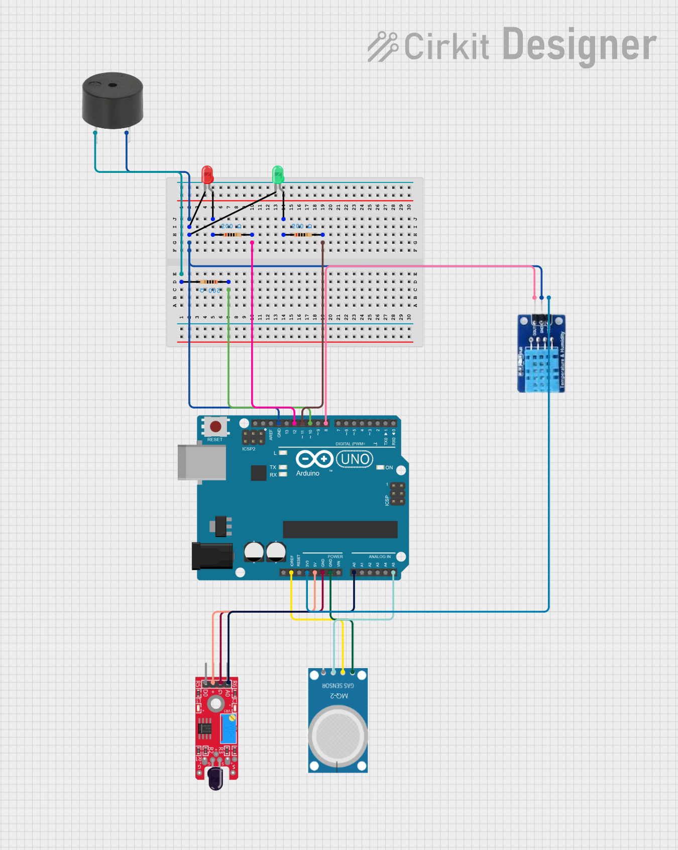
Arduino UNO-Based Environmental Monitoring System with Flame and Gas Detection
Circuit Documentation
Summary
This document provides a detailed overview of a circuit that includes an Arduino UNO microcontroller, various sensors, LEDs, resistors, and a buzzer. The circuit is designed to interface with multiple sensors and output devices, providing a comprehensive setup for monitoring and signaling.
Component List
Resistor
- Description: A resistor with a resistance of 200 Ohms.
- Pins: pin1, pin2
Arduino UNO
- Description: A microcontroller board based on the ATmega328P.
- Pins: UNUSED, IOREF, Reset, 3.3V, 5V, GND, Vin, A0, A1, A2, A3, A4, A5, SCL, SDA, AREF, D13, D12, D11, D10, D9, D8, D7, D6, D5, D4, D3, D2, D1, D0
LED: Two Pin (red)
- Description: A red LED with two pins.
- Pins: cathode, anode
LED: Two Pin (green)
- Description: A green LED with two pins.
- Pins: cathode, anode
Buzzer
- Description: A buzzer with two pins.
- Pins: PIN, GND
MQ-2
- Description: A gas sensor with four pins.
- Pins: GND, VCC, ANALOG, Digital
KY-026 Flame Sensor
- Description: A flame sensor with four pins.
- Pins: AO, GND, VCC, DO
DHT11
- Description: A temperature and humidity sensor with three pins.
- Pins: DATA, GND, VCC
Wiring Details
Resistor
- Pin1: Connected to the anode of the red LED.
- Pin2: Connected to pin D12 of the Arduino UNO.
Resistor
- Pin1: Connected to the anode of the green LED.
- Pin2: Connected to pin D11 of the Arduino UNO.
Resistor
- Pin1: Connected to pin D10 of the Arduino UNO.
- Pin2: Connected to the PIN of the buzzer.
Arduino UNO
- GND: Connected to the cathode of the red LED, the cathode of the green LED, the GND of the DHT11, and the GND of the buzzer.
- D10: Connected to pin1 of a resistor.
- D11: Connected to pin2 of a resistor.
- D12: Connected to pin2 of a resistor.
- IOREF: Connected to the VCC of the MQ-2.
- 3.3V: Connected to the VCC of the DHT11.
- 5V: Connected to the VCC of the KY-026 Flame Sensor.
- A0: Connected to the AO of the KY-026 Flame Sensor.
- A5: Connected to the ANALOG of the MQ-2.
- D8: Connected to the DATA of the DHT11.
LED: Two Pin (red)
- Cathode: Connected to the GND of the Arduino UNO.
- Anode: Connected to pin1 of a resistor.
LED: Two Pin (green)
- Cathode: Connected to the GND of the Arduino UNO.
- Anode: Connected to pin1 of a resistor.
Buzzer
- PIN: Connected to pin2 of a resistor.
- GND: Connected to the GND of the Arduino UNO.
MQ-2
- GND: Connected to the GND of the Arduino UNO.
- VCC: Connected to the IOREF of the Arduino UNO.
- ANALOG: Connected to A5 of the Arduino UNO.
- Digital: Not connected.
KY-026 Flame Sensor
- AO: Connected to A0 of the Arduino UNO.
- GND: Connected to the GND of the Arduino UNO.
- VCC: Connected to the 5V of the Arduino UNO.
- DO: Not connected.
DHT11
- DATA: Connected to D8 of the Arduino UNO.
- GND: Connected to the GND of the Arduino UNO.
- VCC: Connected to the 3.3V of the Arduino UNO.
Code Documentation
Arduino UNO Code
void setup() {
  // put your setup code here, to run once:

}

void loop() {
  // put your main code here, to run repeatedly:

}
This code is a basic template for the Arduino UNO. The setup() function is used to initialize any settings or configurations, and the loop() function contains the main code that runs repeatedly.
This concludes the documentation for the circuit. If you have any questions or need further details, please refer to the specific sections above.