
Arduino Mega ADK-Based Autonomous Robot with Multiple Sensors and Motor Control
View and Edit Project In Cirkit Designer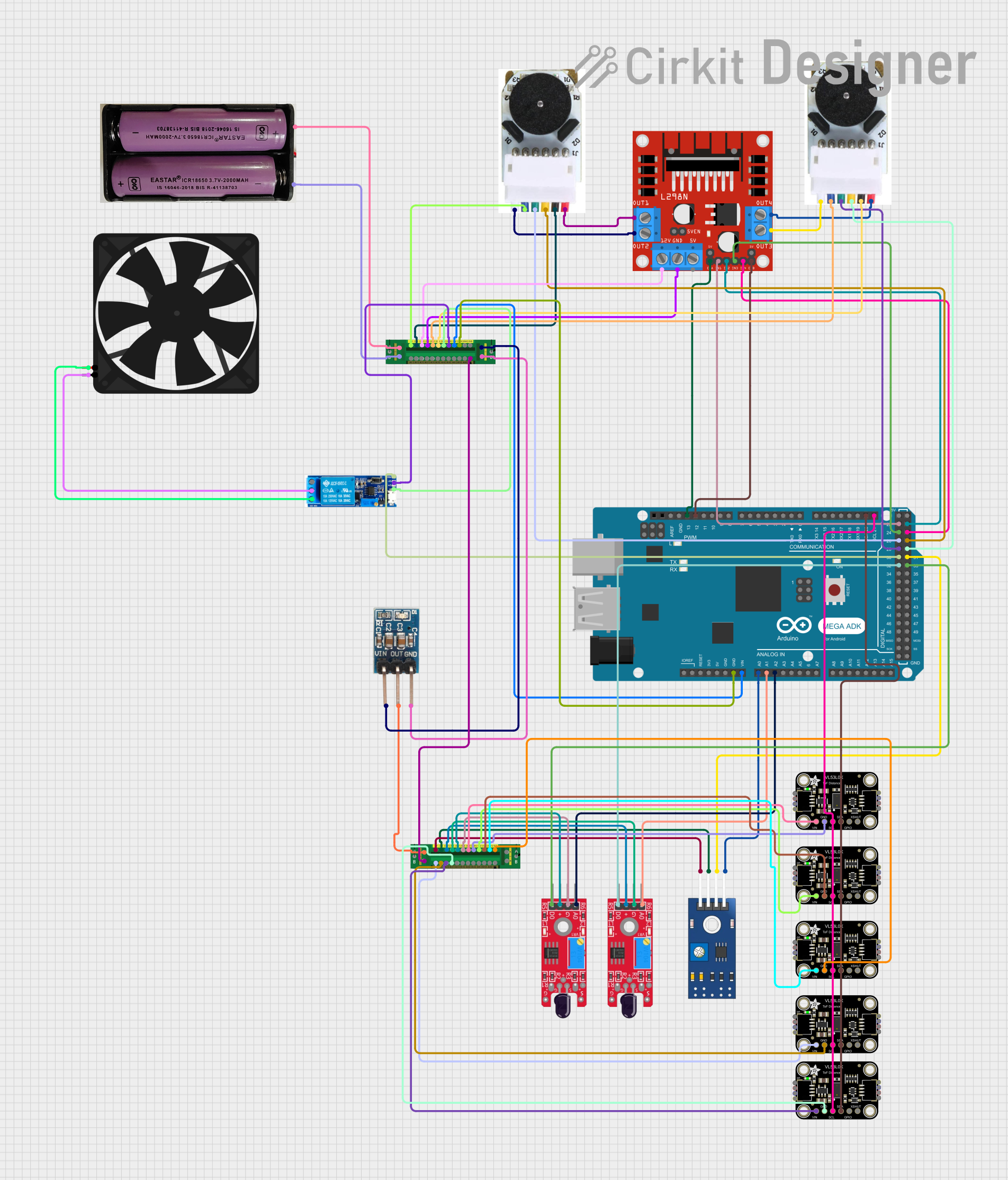
Circuit Documentation
Summary
This document provides a detailed overview of a circuit design that includes an Arduino Mega ADK (Rev3) microcontroller, various sensors, motor drivers, motors, a relay module, a fan, and power distribution boards. The circuit is designed to interface multiple sensors and actuators with the Arduino Mega ADK for various control and monitoring applications.
Component List
Arduino Mega ADK (Rev3)
- Description: A microcontroller board based on the ATmega2560.
- Pins: A0-A15, D0-D53, ICSP, RESET, 3V3, 5V, GND, VIN, IOREF, USB
L298N DC Motor Driver
- Description: A dual H-Bridge motor driver.
- Pins: OUT1, OUT2, 12V, GND, 5V, OUT3, OUT4, ENA, IN1, IN2, IN3, IN4, ENB
TCRT 5000 IR Sensor
- Description: An infrared sensor for object detection.
- Pins: VCC, GND, DO, AO
DC Motor with Encoder
- Description: A DC motor with an integrated encoder for position feedback.
- Pins: Encoder A, Encoder B, GND - Encoder, VCC - Encoder Power, Motor +ve, Motor -ve
Adafruit VL53L0X Time of Flight Distance Sensor
- Description: A sensor for measuring distance using time-of-flight technology.
- Pins: VCC, GND, SCL, SDA, GPIO, XSHUT
KY-026 Flame Sensor
- Description: A sensor for detecting flame.
- Pins: AO, GND, VCC, DO
Fan
- Description: A cooling fan.
- Pins: GND, 5V
Relay Module 5V-30V
- Description: A relay module for switching high voltage devices.
- Pins: Common contact, Normally open, Normally closed, Trigger, V-, V+
7.4V Battery
- Description: A 7.4V power source.
- Pins: +, -
Power Distribution Board
- Description: A board for distributing power to various components.
- Pins: Input +, Input -, Output 1+ to Output 12+, Output 1- to Output 12-
3.3V Regulator
- Description: A voltage regulator for providing 3.3V output.
- Pins: GND, OUT, Vin
Wiring Details
Arduino Mega ADK (Rev3)
- A0: Connected to AO of TCRT 5000 IR Sensor
- A1: Connected to AO of KY-026 Flame Sensor
- A2: Connected to AO of KY-026 Flame Sensor
- D21/SCL: Connected to SCL of all Adafruit VL53L0X Time of Flight Distance Sensors
- D20/SDA: Connected to SDA of all Adafruit VL53L0X Time of Flight Distance Sensors
- D13 PWM: Connected to ENA of L298N DC Motor Driver
- D12 PWM: Connected to ENB of L298N DC Motor Driver
- GND: Connected to Output 11- of Power Distribution Board
- VIN: Connected to Output 11+ of Power Distribution Board
- D22: Connected to IN1 of L298N DC Motor Driver
- D23: Connected to IN2 of L298N DC Motor Driver
- D24: Connected to IN3 of L298N DC Motor Driver
- D25: Connected to IN4 of L298N DC Motor Driver
- D26: Connected to Encoder B of DC Motor with Encoder
- D27: Connected to Encoder A of DC Motor with Encoder
- D28: Connected to Encoder B of another DC Motor with Encoder
- D29: Connected to Encoder A of another DC Motor with Encoder
- D30: Connected to Trigger of Relay Module
- D31: Connected to DO of TCRT 5000 IR Sensor
- D32: Connected to DO of KY-026 Flame Sensor
- D33: Connected to DO of KY-026 Flame Sensor
L298N DC Motor Driver
- OUT1: Connected to Motor +ve of DC Motor with Encoder
- OUT2: Connected to Motor -ve of DC Motor with Encoder
- 12V: Connected to Output 8+ of Power Distribution Board
- GND: Connected to Output 8- of Power Distribution Board
- OUT3: Connected to Motor -ve of another DC Motor with Encoder
- OUT4: Connected to Motor +ve of another DC Motor with Encoder
- ENA: Connected to D13 PWM of Arduino Mega ADK
- ENB: Connected to D12 PWM of Arduino Mega ADK
- IN1: Connected to D22 of Arduino Mega ADK
- IN2: Connected to D23 of Arduino Mega ADK
- IN3: Connected to D24 of Arduino Mega ADK
- IN4: Connected to D25 of Arduino Mega ADK
TCRT 5000 IR Sensor
- VCC: Connected to Output 7+ of Power Distribution Board
- GND: Connected to Output 7- of Power Distribution Board
- DO: Connected to D31 of Arduino Mega ADK
- AO: Connected to A0 of Arduino Mega ADK
DC Motor with Encoder
- Encoder B: Connected to D26 of Arduino Mega ADK
- Encoder A: Connected to D27 of Arduino Mega ADK
- GND - Encoder: Connected to Output 7- of Power Distribution Board
- VCC - Encoder Power: Connected to Output 7+ of Power Distribution Board
- Motor +ve: Connected to OUT1 of L298N DC Motor Driver
- Motor -ve: Connected to OUT2 of L298N DC Motor Driver
Another DC Motor with Encoder
- Encoder B: Connected to D28 of Arduino Mega ADK
- Encoder A: Connected to D29 of Arduino Mega ADK
- GND - Encoder: Connected to Output 9- of Power Distribution Board
- VCC - Encoder Power: Connected to Output 9+ of Power Distribution Board
- Motor +ve: Connected to OUT4 of L298N DC Motor Driver
- Motor -ve: Connected to OUT3 of L298N DC Motor Driver
Adafruit VL53L0X Time of Flight Distance Sensor
- VCC: Connected to various outputs of Power Distribution Board
- GND: Connected to various outputs of Power Distribution Board
- SCL: Connected to D21/SCL of Arduino Mega ADK
- SDA: Connected to D20/SDA of Arduino Mega ADK
KY-026 Flame Sensor
- GND: Connected to various outputs of Power Distribution Board
- VCC: Connected to various outputs of Power Distribution Board
- DO: Connected to D32 and D33 of Arduino Mega ADK
- AO: Connected to A1 and A2 of Arduino Mega ADK
Fan
- GND: Connected to Common contact of Relay Module
- 5V: Connected to Normally closed contact of Relay Module
Relay Module 5V-30V
- Common contact: Connected to GND of Fan
- Normally closed: Connected to 5V of Fan
- Trigger: Connected to D30 of Arduino Mega ADK
- V-: Connected to Output 10- of Power Distribution Board
- V+: Connected to Output 10+ of Power Distribution Board
7.4V Battery
- +: Connected to Input + of Power Distribution Board
- -: Connected to Input - of Power Distribution Board
Power Distribution Board
- Input +: Connected to + of 7.4V Battery
- Input -: Connected to - of 7.4V Battery
- Output 1+ to Output 12+: Connected to various VCC pins of sensors and components
- Output 1- to Output 12-: Connected to various GND pins of sensors and components
3.3V Regulator
- GND: Connected to Output - of Power Distribution Board
- OUT: Connected to Input + of Power Distribution Board
- Vin: Connected to Output + of Power Distribution Board
Code
No code is provided for this circuit.
This document provides a comprehensive overview of the circuit design, including a detailed list of components and their wiring connections. This should serve as a useful reference for building and troubleshooting the circuit.