Multi-Gas Detection System with Arduino and MQ Sensors

Circuit Documentation
Summary
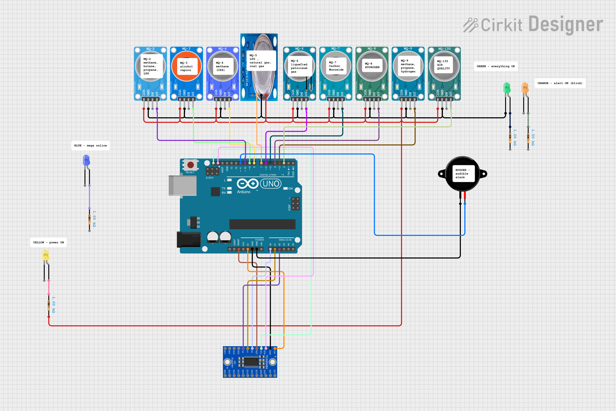
This circuit comprises a series of gas sensors, LEDs, a piezo speaker, a multiplexer, and an Arduino UNO microcontroller. The gas sensors are designed to detect various gases, including methane, LPG, air quality, alcohol, hydrogen, carbon monoxide, and combustible gases. The LEDs serve as indicators, and the piezo speaker is likely used for audible alerts. The Adafruit TCA9548A multiplexer is used to expand the number of I2C devices that can be connected to the Arduino UNO. The Arduino UNO serves as the central processing unit, interfacing with the sensors and controlling the outputs based on sensor readings.
Component List
- MQ Series Gas Sensors: A collection of sensors designed to detect different types of gases. Each sensor has a VCC, GND, and one or two signal outputs (analog and/or digital).
- Piezo Speaker: An electronic device that can produce sound when an electrical signal is applied.
- LEDs (Green, Orange, Blue, Yellow): Light-emitting diodes used as visual indicators.
- Resistors (1k Ohms): Used to limit current to the LEDs.
- Arduino UNO: A microcontroller board based on the ATmega328P, used for controlling the sensors and outputs.
- Adafruit TCA9548A: An I2C multiplexer that allows multiple I2C devices to be connected to the same I2C bus without address conflicts.
Wiring Details
MQ Series Gas Sensors
- VCC: Connected to the 5V supply from the Arduino UNO.
- GND: Connected to the ground (GND) on the Arduino UNO.
- A0: Analog output (not wired in this circuit).
- D0: Digital output connected to various digital pins on the Arduino UNO.
Piezo Speaker
- Pin1 (GND): Connected to the ground (GND) on the Arduino UNO.
- Pin2: Connected to digital pin D11 on the Arduino UNO.
LEDs
- Anode: Connected to the anode side of the LED.
- Cathode: Connected to the cathode side of the LED through a 1k Ohm resistor to the ground (GND) on the Arduino UNO.
Resistors (1k Ohms)
- Pin1: Connected to the anode of the corresponding LED.
- Pin2: Connected to the digital pins on the Arduino UNO for the green LED and to the ground (GND) for the other LEDs.
Arduino UNO
- 5V and GND: Power supply connections for the sensors and multiplexer.
- Digital Pins (D2-D11): Connected to various components including sensors and the piezo speaker.
- Analog Pins (A0-A2): Connected to the Adafruit TCA9548A multiplexer.
- I2C Pins (SDA, SCL): Connected to the INPUTSDA and INPUTSCL pins on the Adafruit TCA9548A multiplexer.
Adafruit TCA9548A
- VCC: Connected to the 5V supply from the Arduino UNO.
- GND: Connected to the ground (GND) on the Arduino UNO.
- RESET: Connected to the Reset pin on the Arduino UNO.
- A0, A1, A2: Connected to the analog pins A0, A1, A2 on the Arduino UNO.
- INPUTSDA, INPUTSCL: Connected to the I2C pins SDA, SCL on the Arduino UNO.
- 0SDA, 0SCL to 7SDA, 7SCL: Not wired in this circuit.
Documented Code
Arduino UNO Code (sketch.ino)
void setup() {
  // put your setup code here, to run once:

}

void loop() {
  // put your main code here, to run repeatedly:

}
This code is a template and does not contain any functional code. It consists of two functions: setup(), which runs once when the Arduino is powered on or reset, and loop(), which runs continuously as long as the Arduino is powered. To control the sensors and outputs, code needs to be added to initialize the pins as inputs or outputs in the setup() function and to read the sensors and control the LEDs and piezo speaker in the loop() function.