
ESP32-CAM and IR Sensor Interface with USB UART Communication
View and Edit Project In Cirkit Designer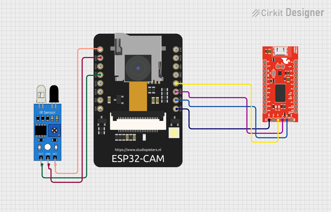
Circuit Documentation
Summary
The circuit in question is designed to interface an ESP32 CAM module with an IR sensor and a SparkFun USB UART Breakout board. The ESP32 CAM is a small-sized camera module that can be used for various IoT applications. It is powered by a 5V supply and communicates with the IR sensor and the USB UART Breakout board for data transmission. The IR sensor is used to detect infrared light, and its output is connected to one of the GPIO pins of the ESP32 CAM. The USB UART Breakout board facilitates serial communication between the ESP32 CAM and a computer or other USB host devices.
Component List
IR Sensor
- Pins: out, gnd, vcc
- Description: An infrared sensor used for detecting IR signals.
SparkFun USB UART Breakout - CY7C65213
- Pins: D+, D-, CTS, DTR, GND, RXD, TXD, VCCIO, DCD, DSR, RI, RTS, 3.3V, 5V, GPIO0, GPIO1, GPIO2, GPIO3, GPIO4, GPIO5, GPIO6, GPIO7
- Description: A USB to serial UART interface board that provides easy serial communication with computers and other devices.
ESP32 CAM
- Pins: 5V, GND, GPIO12, GPIO13, GPIO15, GPIO14, GPIO2, GPIO4, 3.3V, GPIO16, GPIO0, 3.3V / 5V / P_OUT, GPIO3 / RX, GPIO1 / TX
- Description: A small camera module with Wi-Fi capabilities, suitable for IoT applications and image processing.
Wiring Details
IR Sensor
- VCC: Connected to the 5V pin of the ESP32 CAM.
- GND: Connected to the GND pin of the ESP32 CAM.
- OUT: Connected to the GPIO13 pin of the ESP32 CAM.
SparkFun USB UART Breakout - CY7C65213
- VCCIO: Connected to the 3.3V / 5V / P_OUT pin of the ESP32 CAM.
- GND: Connected to the GND pin of the ESP32 CAM.
- TXD: Connected to the GPIO3 / RX pin of the ESP32 CAM.
- RXD: Connected to the GPIO1 / TX pin of the ESP32 CAM.
ESP32 CAM
- 5V: Provides power to the IR sensor.
- GND: Common ground for the IR sensor and the USB UART Breakout board.
- GPIO13: Receives the output signal from the IR sensor.
- 3.3V / 5V / P_OUT: Provides power to the USB UART Breakout board.
- GPIO3 / RX: Receives transmitted data from the USB UART Breakout board's TXD pin.
- GPIO1 / TX: Transmits data to the USB UART Breakout board's RXD pin.
Documented Code
No code has been provided for the microcontrollers in the circuit. If code is later provided, it should be documented here with explanations of how it interacts with the hardware components and any relevant algorithms or communication protocols used.