
Wireless Sensor-Integrated Robotic Vehicle with Dual Arduino Control
View and Edit Project In Cirkit Designer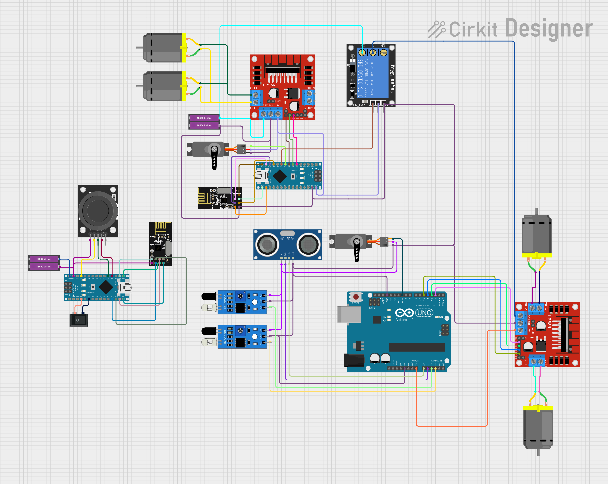
Circuit Documentation
Summary
This document provides a comprehensive overview of a circuit that includes microcontrollers (Arduino Nano and Arduino UNO), wireless communication modules (NRF24L01), motor drivers (L298N), power sources (18650 Li-ion Batteries), and various sensors and actuators. The circuit is designed to control DC motors, read sensor inputs, and communicate wirelessly, which suggests its use in robotics or remote-controlled devices.
Component List
Microcontrollers
- Arduino Nano: A compact board based on the ATmega328P microcontroller, featuring digital and analog I/O pins.
- Arduino UNO: A microcontroller board based on the ATmega328P, with a variety of digital and analog inputs, as well as serial communication capabilities.
Communication Modules
- NRF24L01: A 2.4GHz wireless transceiver module for enabling wireless communication between devices.
Motor Drivers
- L298N DC Motor Driver: A high-power motor driver capable of driving up to four DC motors or two stepper motors.
Power Sources
- 18650 Li-ion Battery x 2: A pair of rechargeable lithium-ion batteries providing a power source for the circuit.
Sensors and Actuators
- HC-SR04 Ultrasonic Sensor: An ultrasonic ranging module for distance measurement.
- IR Sensor: An infrared sensor for detecting proximity or receiving IR signals.
- Servo: A rotary actuator or motor for precise control of angular position.
- KY-023 Dual Axis Joystick Module: A joystick with two axes of control and a pushbutton switch.
- 1-Channel Relay (5V 10A): An electromechanical switch module that allows control of high power devices.
Other Components
- Rocker Switch (SPST): A single-pole single-throw switch used to control power to a circuit.
- DC Motor: An electric motor that runs on direct current electricity.
Wiring Details
Arduino Nano
- GND: Connected to the ground of the power source and common ground with other components.
- D3: Connected to the Rocker Switch and L298N motor driver's IN2.
- D9: Connected to the CE pin of the NRF24L01 module.
- D10: Connected to the CSN pin of the NRF24L01 module.
- D11/MOSI: Connected to the MOSI pin of the NRF24L01 module.
- D12/MISO: Connected to the MISO pin of the NRF24L01 module.
- VIN: Connected to the positive terminal of the 18650 Li-ion Battery.
- 5V: Connected to the KY-023 Joystick Module and other 5V required components.
- A0: Connected to the VRy pin of the KY-023 Joystick Module.
- A1: Connected to the VRx pin of the KY-023 Joystick Module.
- 3V3: Connected to the VCC (3V) of the NRF24L01 module.
- D13/SCK: Connected to the SCK pin of the NRF24L01 module.
Arduino UNO
- GND: Common ground with other components.
- 5V: Power supply to various 5V components.
- Vin: Connected to the power input of the L298N motor driver.
- A0: Connected to the ECHO pin of the HC-SR04 Ultrasonic Sensor.
- A1: Connected to the TRIG pin of the HC-SR04 Ultrasonic Sensor.
- A2: Connected to the output of an IR sensor.
- A3: Connected to the output of another IR sensor.
- D2: Connected to the IN1 of the L298N motor driver.
- D3: Connected to the IN2 of the L298N motor driver.
- D4: Connected to the IN3 of the L298N motor driver.
- D5: Connected to the IN4 of the L298N motor driver.
- D10: Connected to the PWM pin of a Servo.
NRF24L01
- CE: Connected to D9 on the Arduino Nano.
- CSN: Connected to D10 on the Arduino Nano.
- MOSI: Connected to D11/MOSI on the Arduino Nano.
- MISO: Connected to D12/MISO on the Arduino Nano.
- GND: Common ground with the Arduino Nano.
- VCC (3V): Connected to 3V3 on the Arduino Nano.
- SCK: Connected to D13/SCK on the Arduino Nano.
L298N DC Motor Driver
- IN1, IN2, IN3, IN4: Control inputs connected to various digital pins on the Arduino boards.
- ENA, ENB: Enable pins for motor control, connected to PWM-capable pins on the Arduino boards.
- OUT1, OUT2, OUT3, OUT4: Outputs connected to the DC Motors.
- GND: Common ground with the Arduino boards.
- 5V: Power input for the logic part of the motor driver, connected to 5V on the Arduino boards.
- 12V: Power input for the motor part of the motor driver, connected to the positive terminal of the 18650 Li-ion Battery.
Other Components
- Rocker Switch (SPST): Switches the ground connection to the Arduino Nano.
- DC Motors: Connected to the outputs of the L298N motor drivers.
- HC-SR04 Ultrasonic Sensor: VCC connected to 5V, TRIG and ECHO connected to the Arduino UNO.
- IR Sensors: OUT connected to analog pins on the Arduino UNO, VCC connected to 5V, GND to common ground.
- Servos: PWM connected to digital pins on the Arduino boards, VCC to 5V, and GND to common ground.
- KY-023 Joystick Module: VRx and VRy connected to analog pins on the Arduino Nano, SW not used, GND to common ground, and +5V to 5V on the Arduino Nano.
- 1-Channel Relay: Signal connected to a digital pin on the Arduino Nano, power to 5V, ground to common ground, NC, C, and NO used for switching external devices.
Documented Code
Arduino Nano (Instance 1)
void setup() {
  // put your setup code here, to run once:

}

void loop() {
  // put your main code here, to run repeatedly:

}
Arduino Nano (Instance 2)
void setup() {
  // put your setup code here, to run once:

}

void loop() {
  // put your main code here, to run repeatedly:

}
Arduino UNO
void setup() {
  // put your setup code here, to run once:

}

void loop() {
  // put your main code here, to run repeatedly:

}
This document provides a basic framework for the circuit's documentation. Further details such as the purpose of each part in the circuit, specific properties of components, and the actual implementation code for the microcontrollers would be necessary to complete the documentation.