
ESP32-Based Environmental Monitoring System with Solar Charging
View and Edit Project In Cirkit Designer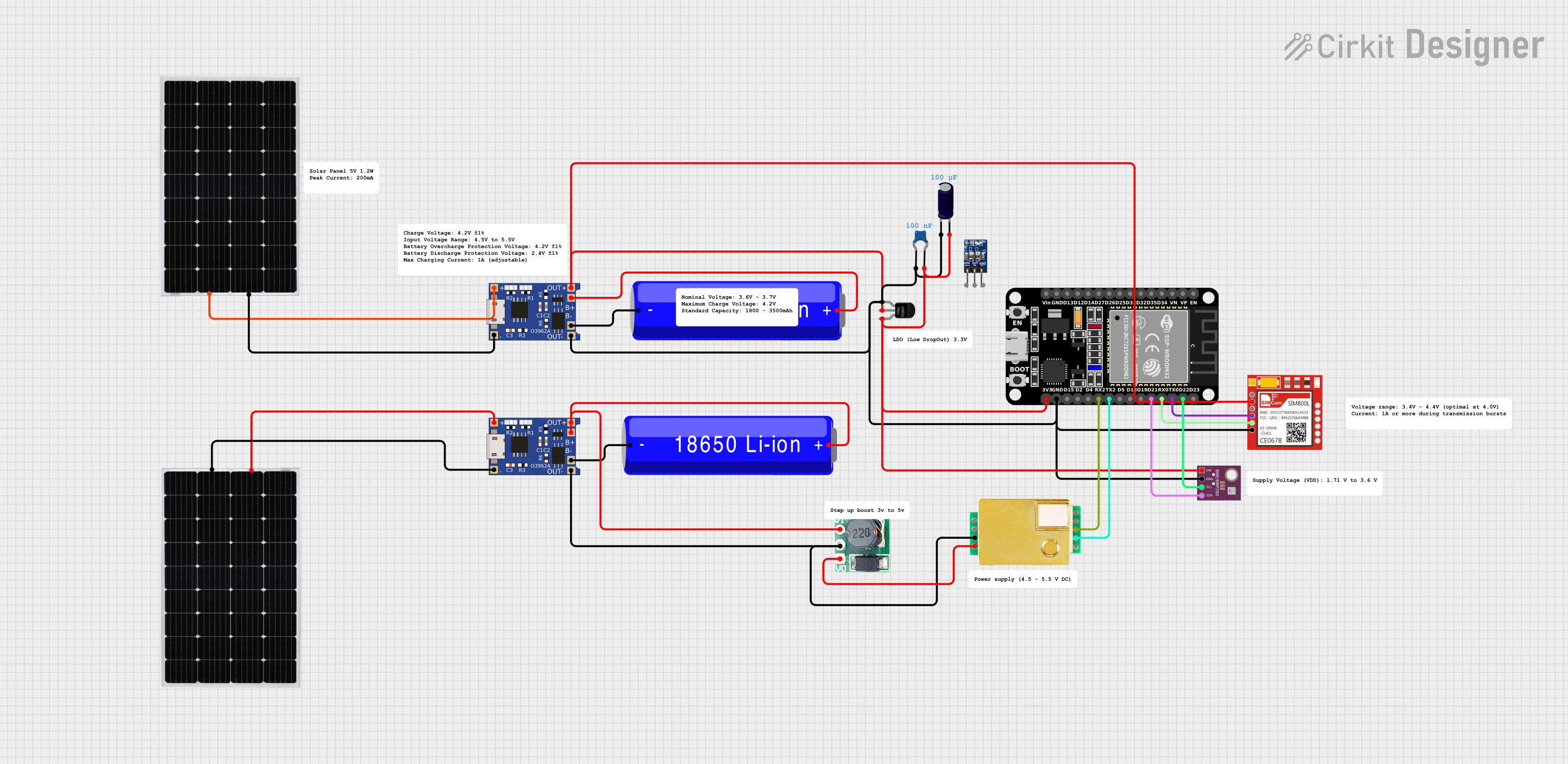
Circuit Documentation
Summary
The circuit in question appears to be a sensor and communication system, possibly for environmental monitoring and data transmission. It includes a BME/BMP280 sensor for measuring temperature, humidity, and pressure, an MH-Z19B sensor for CO2 measurement, a SIM800L module for GSM communication, and an ESP32 microcontroller for data processing and control. The circuit is powered by solar panels charging 18650 Li-ion batteries through TP4056 charging modules, with voltage regulation provided by a generic voltage regulator and a step-up boost converter. Capacitors are included for power supply stabilization.
Component List
Sensors
- BME/BMP280: A sensor for measuring temperature, humidity, and atmospheric pressure.
- MH-Z19B: An infrared CO2 sensor for carbon dioxide detection.
Communication
- Sim800l: A GSM/GPRS module for cellular network communication.
Power Management
- TP4056: A lithium battery charger module for charging 18650 Li-ion batteries.
- Voltage Regulator: A device to maintain a constant voltage level.
- Step Up Boost 3v- 5v: A DC-DC converter to step up the voltage from 3V to 5V.
- Solar Panel: A photovoltaic panel for converting solar energy into electrical energy.
- 18650 Li-ion Battery: A rechargeable battery for energy storage.
Microcontroller
- ESP32 (30 pin): A microcontroller with Wi-Fi and Bluetooth capabilities for managing sensors and communication modules.
Passive Components
- Ceramic Capacitor: A small-value capacitor for filtering and decoupling.
- Electrolytic Capacitor: A larger-value capacitor for power supply smoothing.
Voltage Regulation
- ams1117 3.3: A low dropout voltage regulator that outputs 3.3V.
Wiring Details
BME/BMP280
- GND: Connected to the system ground.
- SCL: Connected to ESP32 pin D22 for I2C communication.
- SDA: Connected to ESP32 pin D21 for I2C communication.
- VIN: Connected to the 3.3V power rail.
MH-Z19B
- TX: Connected to ESP32 pin RX2 for serial communication.
- RX: Connected to ESP32 pin TX2 for serial communication.
- GND: Connected to the system ground.
- Vin: Connected to the output of the Step Up Boost 3v- 5v module.
Sim800l
- GND: Connected to the system ground.
- VCC: Connected to the output of the Voltage Regulator.
- RXD: Connected to ESP32 pin TX0 for serial communication.
- TXD: Connected to ESP32 pin RX0 for serial communication.
TP4056
- OUT-: Connected to the system ground.
- B-: Connected to the negative terminal of the 18650 Li-ion Battery.
- B+: Connected to the positive terminal of the 18650 Li-ion Battery.
- OUT+: Connected to the input of the Voltage Regulator and the Step Up Boost 3v- 5v module.
- IN-: Connected to the negative terminal of the Solar Panel.
- IN+: Connected to the positive terminal of the Solar Panel.
Ceramic Capacitor
- One pin connected to BME/BMP280 VIN.
- The other pin connected to the system ground.
Electrolytic Capacitor
- Negative terminal connected to the system ground.
- Positive terminal connected to the 3.3V power rail.
Solar Panel
- Positive terminal connected to TP4056 IN+.
- Negative terminal connected to TP4056 IN-.
18650 Li-ion Battery
- Positive terminal connected to TP4056 B+.
- Negative terminal connected to TP4056 B-.
Voltage Regulator
- GND: Connected to the system ground.
- IN: Connected to TP4056 OUT+.
- OUT: Connected to the 3.3V power rail.
Step Up Boost 3v- 5v
- GND: Connected to the system ground.
- Vi: Connected to TP4056 OUT+.
- Vo: Connected to MH-Z19B Vin.
ESP32 (30 pin)
- GND: Connected to the system ground.
- 3V3: Connected to the 3.3V power rail.
- D22: Connected to BME/BMP280 SCL.
- D21: Connected to BME/BMP280 SDA.
- RX2: Connected to MH-Z19B TX.
- TX2: Connected to MH-Z19B RX.
- TX0: Connected to Sim800l RXD.
- RX0: Connected to Sim800l TXD.
Documented Code
No code was provided for the microcontroller(s) in the circuit. The documentation of the code would typically include descriptions of the functions, algorithms, and communication protocols used, as well as any initialization and main loop routines. It would also detail how the microcontroller interfaces with the sensors and communication modules, including any libraries or external resources used.