
Solar-Powered STM32-Based Automation System with Matrix Keypad and RTC
View and Edit Project In Cirkit Designer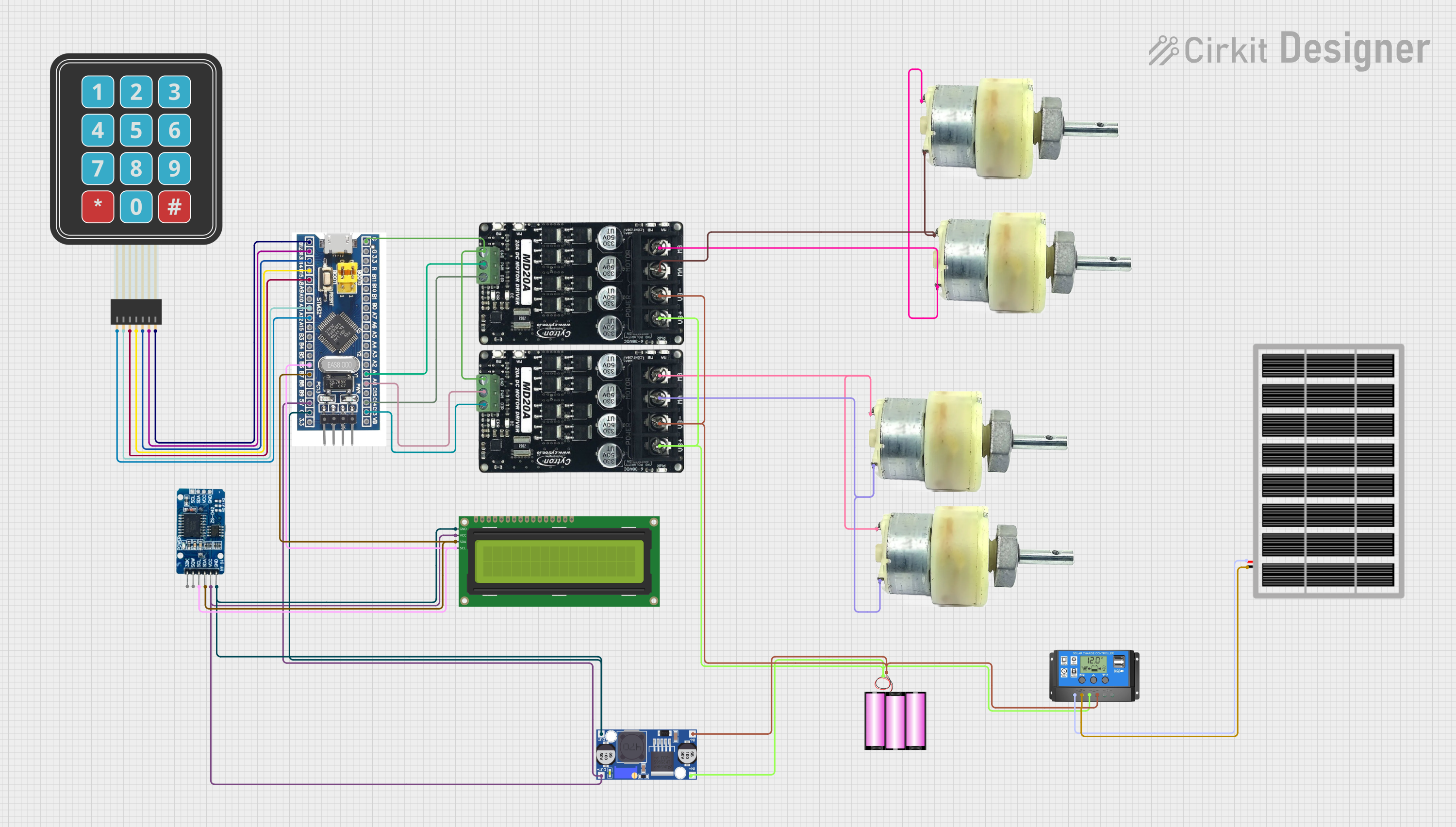
Circuit Documentation
Summary
This circuit is designed to control a set of 12V geared motors using MD20 Cytron motor drivers, which are interfaced with an STM32F103C8T6 microcontroller. The system also includes a membrane matrix keypad for user input, a real-time clock (RTC DS3231) for timekeeping, and a 16x2 I2C LCD for display purposes. Power management is handled by a buck converter, which steps down voltage from a 12V battery that is charged via a solar panel connected through a solar charge controller.
Component List
STM32F103C8T6 Microcontroller
- A 32-bit ARM Cortex-M3 microcontroller used for controlling the various components in the circuit.
Membrane Matrix Keypad
- A simple interface for user input, with rows and columns to detect button presses.
RTC DS3231
- A highly accurate I2C real-time clock with an integrated temperature-compensated crystal oscillator (TCXO) and crystal.
Buck Converter
- A DC-DC converter that steps down voltage from a higher voltage battery to a lower voltage required by the circuit.
16x2 I2C LCD
- A liquid crystal display that can show 16 characters per line and has 2 lines, with an I2C interface for communication.
MD20 Cytron Motor Driver (x2)
- A motor driver capable of driving a DC motor with a high current rating, controlled via PWM and direction inputs.
12V Geared Motor (x4)
- A DC motor with a gearbox to provide a high torque output suitable for various mechanical applications.
12V Battery
- A rechargeable battery providing the power source for the circuit.
Solar Charge Controller
- A device that controls the charging of the battery from the solar panel and protects against overcharging.
Solar Panel
- A photovoltaic panel that converts sunlight into electrical energy to charge the battery.
Wiring Details
STM32F103C8T6 Microcontroller
- GND: Connected to the ground plane.
- 5V: Powers the RTC DS3231, 16x2 I2C LCD, and the buck converter.
- A0, A1: PWM outputs to the MD20 Cytron motor drivers.
- C13, C14: Direction control outputs to the MD20 Cytron motor drivers.
- B6, B7: I2C communication (SCL, SDA) with RTC DS3231 and 16x2 I2C LCD.
- B12, B13, B14, B15, A8, A11, A12: Connected to the membrane matrix keypad for detecting key presses.
Membrane Matrix Keypad
- Rows and Columns: Connected to the STM32F103C8T6 for user input detection.
RTC DS3231
- GND: Connected to the ground plane.
- VCC: Powered by the 5V output from the buck converter.
- SCL, SDA: I2C communication with the STM32F103C8T6 and 16x2 I2C LCD.
Buck Converter
- IN+, IN-: Input from the 12V battery.
- OUT+, OUT-: Output 5V to power the STM32F103C8T6, RTC DS3231, and 16x2 I2C LCD.
16x2 I2C LCD
- GND: Connected to the ground plane.
- VCC: Powered by the 5V output from the buck converter.
- SCL, SDA: I2C communication with the STM32F103C8T6 and RTC DS3231.
MD20 Cytron Motor Driver
- GND: Connected to the ground plane.
- VB+, VB-: Powered by the 12V battery.
- MA, MB: Connected to the terminals of the 12V geared motors.
- PWM: Receives PWM signal from the STM32F103C8T6 for speed control.
- DIR: Receives direction control signal from the STM32F103C8T6.
12V Geared Motor
- Terminal 1, Terminal 2: Connected to the MA and MB outputs of the MD20 Cytron motor drivers.
Battery 12V
- +, -: Provides power to the MD20 Cytron motor drivers and the buck converter.
Solar Charge Controller
- Solar Cell +, Solar Cell -: Connected to the solar panel.
- Battery +, Battery -: Connected to the 12V battery.
- Load +, Load -: Not used in this circuit.
Solar Panel
- VCC, GND: Provides solar energy to the solar charge controller for battery charging.
Documented Code
There is no embedded code provided for the microcontroller. The documentation of the code would typically include details on the initialization of peripherals, the main control loop, interrupt service routines, and any communication protocols used. Since no code is available, this section cannot be completed.